
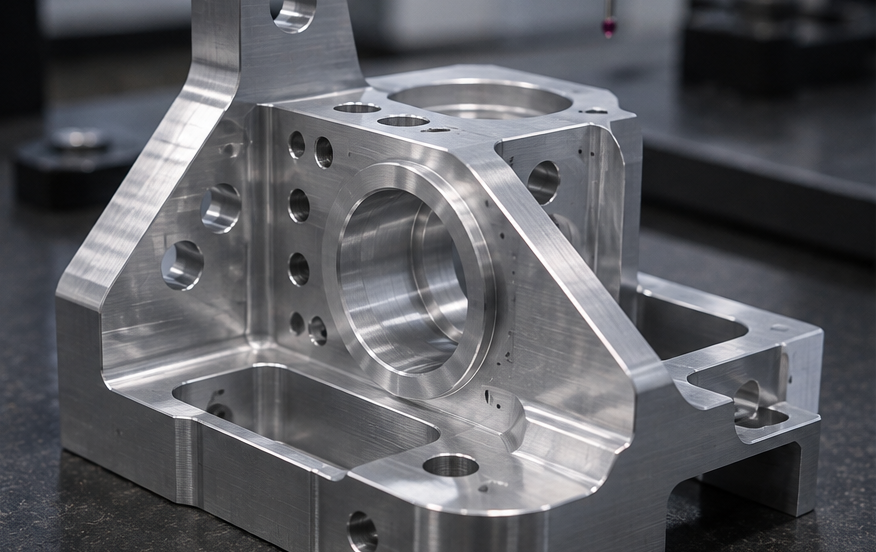
Holes are among the most common features found on CNC-machined components.They can also be among the most functionally important.
A hole may simply provide clearance for a fastener, or it may locate a dowel, carry a bearing, guide a shaft, provide a sealing surface or form part of a precisely aligned assembly. These applications do not all require the same level of accuracy. For this reason, the required CNC hole tolerance should ideally be based on the function of the feature rather than applying the tightest possible tolerance to every hole on the drawing.
Different machining processes can then be selected according to the required diameter, position, roundness, surface finish and production requirements. Drilling may be entirely suitable for one feature. Another may benefit from reaming. A critical bore may require boring or another precision finishing operation. Understanding the differences can help designers and buyers specify machined holes more effectively and avoid unnecessary cost.
Why Hole Accuracy Matters
A hole is rarely important simply because it is round. Its function usually depends on several characteristics working together. These can include:
- diameter;
- position;
- depth;
- straightness;
- roundness;
- cylindricity;
- surface finish;
- relationship to other features;
- perpendicularity to a reference surface.
A clearance hole for a standard bolt may tolerate a relatively generous diameter variation. A hole locating a precision dowel pin may require much tighter control. Likewise, a bearing bore may need accurate diameter, roundness and surface finish because these directly affect how the bearing fits and performs.
When considering CNC hole accuracy, the first question should therefore be:
What does the hole need to do?
The answer determines the level of manufacturing and inspection control that is appropriate.
CNC Drilling
Drilling is the most familiar method of producing holes. A rotating drill enters the material and removes material along its axis. Modern CNC machine tools can position drilled holes accurately and produce them efficiently, making drilling suitable for a wide range of component features. Typical applications include:
- clearance holes;
- tapping holes;
- general fixing holes;
- pilot holes;
- holes that will subsequently be reamed or bored.
However, a drilled hole is not always the final solution where very close dimensional control is required. The finished size and condition can be influenced by the drill geometry, material, tool condition, depth and machining parameters. A drill can also wander slightly as it enters or progresses through material, particularly where machining conditions are difficult. For many ordinary holes this is insignificant. For a high-precision locating or bearing feature, a secondary finishing operation may be more appropriate.
What Accuracy Can CNC Drilling Achieve?
There is no single tolerance that applies to every drilled hole. Accuracy depends on the machine, CNC tooling, hole size, depth, material and component geometry. A short hole in a stable aluminium component can behave very differently from a deep, relatively small-diameter hole in a harder material. The required tolerance should therefore be assessed in the context of the individual component.
It is also important not to confuse machine positioning accuracy with finished hole diameter. A CNC machine may position the drill accurately while the hole itself still reflects the characteristics of the drilling process. This distinction matters when a drawing contains both a diameter tolerance and a positional tolerance. They control different characteristics.
What Is Reaming?
Reaming is a finishing process used to improve the size and surface condition of a previously produced hole. The hole is normally drilled slightly undersize first. A reamer is then passed through it, removing a relatively small amount of material.
Because the reamer is not intended for heavy material removal, the initial hole must provide a suitable starting condition. Reaming can be useful where a more controlled finished diameter is required than would normally be expected from drilling alone. Common applications include:
- dowel holes;
- locating holes;
- pin fits;
- accurate assembly holes;
- certain bush or shaft interfaces.
A reamed hole can provide a consistent diameter and good surface finish when the process is correctly applied. However, reaming is not necessarily the answer for every precision hole.
What Is CNC Boring?
Boring enlarges and finishes an existing hole using a cutting tool. Unlike drilling, which creates the initial hole, boring generally starts with a hole that already exists. 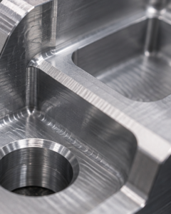
The boring tool then removes material from the internal surface to establish the required diameter and geometry. Boring can be useful for precise bores because the cutting path can be controlled through the CNC machine. It may be selected where requirements include:
- accurate finished diameter;
- improved alignment;
- controlled bore geometry;
- larger hole sizes;
- critical fits.
Boring is widely associated with bearing locations, precision housings and other components where the bore is an important functional feature. As with any process, suitability depends on the part geometry, accessibility and tolerance required.
Drilling Versus Reaming Versus Boring
The three processes have different purposes.
Drilling is primarily a hole-generation process.
Reaming is generally used to size and finish a previously produced hole using a dedicated multi-edge tool.
Boring enlarges and finishes an existing hole using a controlled cutting operation.
A simplified manufacturing sequence might therefore be:
- drill an initial hole;
- leave material for finishing;
- ream or bore the feature to the required final size.
Not every precision hole requires all three stages. The manufacturing process should reflect the engineering requirement. Using a precision finishing operation on every non-critical clearance hole would add cost unnecessarily. Likewise, relying only on drilling for a critical bearing or locating feature may not provide the intended level of control.
Diameter Tolerance
Hole diameter is often the first characteristic designers consider. For example, a drawing may specify a nominal diameter along with upper and lower limits. The tighter those limits become, the more manufacturing control may be required. However, diameter alone does not guarantee function.Two holes could measure the same diameter while differing in:
- position;
- shape;
- surface finish;
- orientation.
This is especially important for precision assemblies. A bore may be dimensionally correct but still fail to align properly with another feature if its position or axis is incorrect. A complete drawing therefore needs to control the characteristics that actually matter to the assembly.
Hole Position and True Position
The location of a hole can be as important as its diameter. This is particularly true where several holes need to align with another component. For example, a series of clearance holes may need to correspond with a matching bolt pattern. Dowel holes may need even tighter positional relationships because they are used to locate parts accurately.
Geometric tolerancing can be used to control the position of a hole relative to defined datums. This allows the drawing to specify where the hole axis must lie rather than relying only on conventional plus-and-minus coordinate dimensions.
For buyers and designers, the important point is that diameter tolerance and position tolerance serve different purposes. Both should reflect the actual function of the feature.
Hole Roundness and Cylindricity
A nominally round hole is not necessarily perfectly circular at every point. Roundness controls how closely a cross-section of the hole conforms to a true circle. Cylindricity controls the form of the entire cylindrical surface.
These geometric requirements can matter for precision bores, sealing surfaces and other critical interfaces. They are not normally required on every drilled hole. Adding demanding geometric controls without a functional reason can increase manufacturing and inspection complexity.
Where the hole is a bearing seat, piston bore or other significant functional feature, additional geometric control may be justified. Again, design intent should determine the specification.
Surface Finish Inside a Hole
The internal surface finish of a hole can matter in many applications. A general clearance hole may not require a particularly refined surface. A bore that interacts with a seal, bearing or sliding component may need much closer control.
Different machining processes naturally produce different surface characteristics. Drilling, reaming and boring do not leave identical finishes. Tool condition, cutting parameters and material also affect the result.
If internal surface finish is functionally important, it should be specified appropriately rather than assumed from the hole tolerance alone. A tight diameter tolerance does not automatically define surface texture.
Fits Between Holes and Shafts
Many precision holes are designed to work with a mating shaft, pin, bearing or bush. The relationship between the hole size and mating component determines the fit. Depending on function and ISO system for tolerances and fits, an assembly may require:
- clearance;
- a close sliding fit;
- accurate location;
- transition fit;
- interference.
Standard fit systems provide established combinations of hole and shaft tolerances. This can be more effective for fits between holes and shafts than inventing arbitrary limits for each component. Designers should consider how the complete assembly needs to behave rather than focusing on the hole in isolation. For example, a locating dowel may require a different fit from a bolt passing through the same component.
Dowel Holes
Dowel holes are a common example of where greater hole accuracy may be required. Dowel pins are used to locate components relative to one another. Unlike ordinary fastening holes, their main purpose is usually positional control rather than simply allowing a screw or bolt to pass through. For this reason, dowel holes may require a controlled diameter and accurate position.
Reaming is one process commonly associated with producing accurate dowel holes. However, the exact manufacturing approach depends on the component and specification. Where two or more dowels are used together in CNC machining, their positional relationship is particularly important because misalignment can make assembly difficult even if the individual hole diameters are correct.
Bearing Bores
Bearing bores can be among the more critical holes found on CNC-machined components. The bore may need to control:
- bearing fit;
- alignment;
- concentricity;
- roundness;
- surface finish;
- relationship with another bearing or shaft feature.
Too much clearance could allow unwanted movement. Too much interference could make assembly difficult or adversely affect the bearing. For this reason, bearing locations should be specified according to the bearing manufacturer’s requirements and the function of the assembly. Machining and inspection methods can then be selected accordingly. A bearing bore is a good example of a feature where simply specifying “Ø30” does not necessarily communicate enough information.
Hole Depth
Depth can significantly influence machinability. A relatively shallow hole is generally easier to access and evacuate chips from than a very deep one. As hole depth increases, several factors become more significant:
- tool rigidity;
- chip evacuation;
- coolant access;
- straightness;
- heat;
- tool wear.
A deep hole with a small diameter may require specialised drilling strategies or tooling. Designers should therefore consider whether the full depth is functionally required. For blind holes, sufficient additional depth may also be required for drill geometry or subsequent threading operations. The ratio between hole diameter and depth can be more important than depth alone.
Through Holes and Blind Holes
A through hole passes completely through the component. A blind hole terminates within the material. Through holes often provide simpler chip evacuation because the tool can break through the opposite side. Blind holes require more consideration at the bottom of the feature.
A standard drill normally leaves a pointed bottom rather than a perfectly flat one. If a design requires a flat-bottomed blind hole, that is a separate geometry requirement and may need additional machining. Likewise, where the exact depth of the cylindrical portion matters, the drawing should communicate this clearly. Small details in hole specification can affect the actual manufacturing route.
Deep Holes and Tool Deflection
Long drilling tools are less rigid than short ones. As tool length increases, the potential for deflection and wandering also increases. This is one reason deep, small-diameter holes can be more challenging than their appearance on a CAD model might suggest. Possible considerations include:
- pilot drilling;
- staged drilling;
- specialised tool geometry;
- controlled peck cycles;
- coolant strategy;
- reduced cutting parameters.
The correct approach depends on the material and geometry. Where a deep hole is not essential to function, reducing depth or increasing diameter may simplify manufacturing significantly.
Intersecting Holes
Some components contain holes that intersect with one another. These are common in manifolds, fluid-control parts and complex engineering components. Intersecting holes introduce additional issues. A drill may encounter an interrupted cut as it breaks into an existing bore. The intersection can also create internal burrs. If flow, cleanliness or internal surface condition matters, those burrs may need particular attention.
The machining supplier must therefore consider not only the dimensions of each individual hole but also the order in which the features are created. This connects closely with deburring and edge-condition requirements.
Threaded Holes
Threaded holes introduce additional considerations beyond basic diameter. The initial drilled hole must be suitable for the required thread, after which the thread may be produced by tapping, thread milling or another appropriate process.
For blind threaded holes, the required usable thread depth may differ from the total drilled depth. Thread size, pitch, position and tolerance also need to be defined clearly. Where threaded holes are used in an accurate assembly, their positional relationship with other features may be just as important as the thread itself. For a deeper explanation, threaded holes should be considered as a separate design and machining subject rather than simply another drilled feature.
Hole Accuracy in Thin-Walled Components
Hole accuracy can become more challenging when the surrounding material is thin or flexible. Cutting forces from drilling, reaming or boring may influence the component.
The workholding used to secure the part can also distort a thin wall. This means the finished hole geometry may depend partly on how the surrounding component behaves during machining. Machining sequence for thin-walled components becomes particularly important. Where possible, critical holes may be produced while the component still has enough rigidity to support the operation effectively. In other cases, the final feature may need to be completed later in the process. The correct strategy depends on the design.
Inspection of CNC Machined Holes
Inspection should match the characteristics specified on the drawing. Simple hole diameters might be checked using:
- plug gauges;
- pin gauges;
- calipers;
- micrometers or bore measurement equipment where appropriate.
More demanding bores may require:
- bore gauges;
- internal micrometers;
- coordinate measuring machines;
- specialist gauging.
Position can be assessed using coordinate measurement or appropriate fixtures. Surface finish may require dedicated surface measurement equipment. The important principle is that machining and inspection should be considered together. There is little value in specifying a tolerance that cannot be measured reliably using an appropriate inspection method.
Avoiding Unnecessarily Tight Hole Tolerances
Tight tolerances have a legitimate place in precision engineering. However, applying them to every hole can add unnecessary cost.
Consider two features on the same component. One is a clearance hole for an M6 bolt. The second locates a precision dowel. It would be unusual for both to need the same diameter control. A relatively generous clearance hole may work perfectly well for the bolt. The dowel location may require considerably tighter dimensional and positional tolerances.
By differentiating between critical and non-critical holes, designers can focus machining and inspection effort where it provides actual functional value. This is a core principle of design for manufacture in precision CNC machining.
How Hole Requirements Can Affect CNC Machining Cost
Hole features can influence cost in several ways. A simple drilled clearance hole may require very little machining time. Cost can increase where the design requires:
- reaming;
- precision boring;
- deep-hole drilling;
- small-diameter deep holes;
- tight positional tolerances;
- demanding surface finish;
- additional inspection;
- numerous tool changes;
- specialist gauges;
- intersecting internal features.
Quantity also matters. A component containing forty precision holes will naturally require more machining and inspection than one containing four. Reviewing the function of each hole can therefore reveal opportunities to simplify manufacturing without compromising performance.
Designing Precision Holes for CNC Machining
Several questions are useful when specifying machined holes.
What does the hole actually do?
Is it clearance, location, bearing support, fluid passage or another function?
How accurate does the diameter need to be?
Base the tolerance on function.
Does its position matter independently of its diameter?
If so, consider appropriate positional control.
Is the hole deeper than necessary?
Additional depth can increase machining complexity.
Is surface finish important?
Specify it separately where required.
Does the hole intersect another feature?
Consider internal burrs and machining sequence.
Does a mating part dictate the fit?
Use appropriate standard fit information where possible.
These questions help establish an economical and technically appropriate specification.
When Should You Discuss Hole Tolerances With Your CNC Supplier?
Most conventional hole features can be quoted directly from a clear drawing. Additional discussion can be useful when the component contains:
- very tight bore tolerances;
- deep holes;
- high aspect-ratio holes;
- bearing fits;
- precision dowel locations;
- multiple aligned bores;
- intersecting internal passages;
- demanding surface finishes;
- thin material around precision holes.
A machining supplier can review the relationship between geometry, tooling, workholding and inspection before production begins. Sometimes a small change to tolerance, depth or feature geometry can simplify the process significantly without affecting component function.
Precision Hole Machining at Tarvin Precision
Drilling a hole may be one of the most familiar machining operations, but precision hole manufacture can involve much more than simply producing a nominal diameter. Position, fit, depth, roundness, surface finish and the relationship with surrounding features can all influence the required manufacturing process.
At Tarvin Precision, we manufacture CNC-machined components containing drilled, reamed, bored and threaded features for a range of demanding engineering applications. Where components contain critical bores, tight positional CNC machining tolerances, deep holes or complex intersecting features, considering these requirements early can help establish a controlled manufacturing and inspection route.
If you have an engineering drawing or CAD model containing precision holes or bores that you would like us to review, contact Tarvin Precision to discuss your requirements.
Frequently Asked Questions
Here are some of the frequently asked questions we hear about CNC hole tolerances.
What is a typical CNC hole tolerance?
There is no single tolerance for every CNC-machined hole. The achievable and appropriate tolerance depends on hole diameter, depth, material, tooling, machining method and the function of the feature.
What is the difference between drilling and reaming?
Drilling creates the initial hole. Reaming is a finishing process that removes a small amount of material from a previously produced hole to improve its final size and surface condition.
What is the difference between reaming and boring?
Reaming uses a multi-edge tool sized for the intended hole, while boring uses a cutting tool to enlarge and finish an existing hole. The most suitable process depends on the required geometry and tolerance.
When should a hole be reamed?
Reaming may be appropriate where a more consistent finished diameter and surface condition is required than drilling alone would normally provide. Dowel and locating holes are common examples.
Why are bearing bores more demanding to machine?
Bearing bores may require close control of diameter, roundness, alignment, surface finish and fit. These characteristics can directly affect bearing installation and performance.
Does a tight hole diameter tolerance guarantee accurate assembly?
No. Hole position, orientation, roundness and the tolerances of the mating component may also affect assembly. Diameter is only one part of the overall requirement.
How are precision CNC holes inspected?
Depending on the requirement, inspection can involve plug gauges, pin gauges, bore gauges, internal measurement equipment, coordinate measuring machines and specialist surface or geometric measurement methods.