
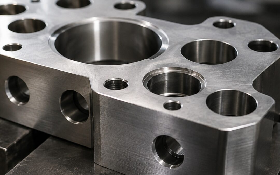
True position is one of the most commonly used geometric tolerances on engineering drawings, particularly for holes, bores, pins and other features that must align correctly within an assembly.
At first glance, it can appear more complicated than a conventional plus-and-minus dimension because it combines basic dimensions, datums and a geometric tolerance zone. In practice, however, the underlying idea is straightforward: true position tolerance controls how far the actual location of a feature is allowed to deviate from its theoretically exact position.
For CNC-machined components, this is particularly important where several features must align with another part. Bolt-hole patterns, dowel locations, bearing bores and locating pins are all common examples.
Understanding true position helps designers communicate functional requirements more clearly and gives machinists and inspectors a better framework for producing and verifying critical feature locations.
What Is True Position Tolerance?
True position is a geometric tolerance used to control the location of a feature relative to a defined reference framework.
The theoretically exact location of the feature is established using basic dimensions, while the allowable variation is defined by the position tolerance shown in the feature control frame.
In many cases, the tolerance zone is cylindrical. This is particularly common for holes and pins. For example, if a hole is intended to lie at a precise X and Y location relative to datums A, B and C, the drawing may define that location using basic dimensions and then apply a position tolerance. The centreline or axis of the actual manufactured hole must fall within the permitted cylindrical tolerance zone.
This differs from traditional plus-and-minus coordinate tolerancing, where X and Y dimensions are each allowed to vary independently. True position combines those location requirements into a single geometric tolerance zone that more closely reflects how the feature functions in an assembly.
Why Is True Position Used?
The main advantage of true position is that it controls feature location in a way that is often more closely related to real assembly requirements.
Consider a plate containing four bolt holes that must align with another component. The exact X and Y position of each hole matters, but what the assembly really needs is for the holes to lie within a region that allows the fasteners to pass through correctly.
A position tolerance defines that allowable region directly. This can provide a more functional and flexible method of specifying hole locations than separate plus-and-minus dimensions. It also helps avoid situations where a hole could technically meet its individual X and Y limits yet still fall outside the region that permits correct assembly.
For designers, the benefit is clearer control of function. For machining suppliers, the drawing gives a more precise description of what matters. For inspectors, the result can be evaluated against a defined geometric tolerance zone.
True Position and Datums
True position is usually referenced to a datum framework. The datums establish the coordinate system from which the theoretically exact location of the feature is defined. For example, a drawing might use:
- datum A as the main mounting face;
- datum B as a side face;
- datum C as another locating feature.
The hole position is then controlled relative to these references. This means datum selection has a direct effect on how position is interpreted. A position tolerance should ideally be referenced to features that reflect how the component is located or assembled in service.
If a mounting face determines how the part sits and a side feature determines lateral position, using those as datums gives the true position requirement a functional basis. This is one reason datum selection and positional tolerancing are closely related topics.
Basic Dimensions and True Position
Basic dimensions define the theoretically exact location of a feature.
Unlike conventional dimensions, they do not carry a plus-and-minus tolerance directly. The allowable variation is instead controlled by the position tolerance. This is an important distinction.
If a hole is shown 25 mm from datum B and 40 mm from datum C using basic dimensions, those values define its ideal location. The actual hole is then allowed to vary within the tolerance zone specified by the feature control frame. This separates the concept of nominal location from permitted variation.
For complex hole patterns, this approach can make the drawing clearer because all features are located theoretically from the same datum system while the geometric tolerance defines how much deviation is acceptable.
True Position for Holes
Holes are probably the most familiar application of position tolerance.
A hole might need to align with a bolt, dowel, bearing, bush or mating component. In each case, its location relative to other features can be more important than its nominal diameter alone.
For a simple clearance hole, the position tolerance may be relatively generous because the bolt has room to move within the hole. For a dowel location, the position requirement may be much tighter because the hole is being used to locate two components precisely. The same principle applies to bearing bores and other precision features.
The correct tolerance therefore depends on the function of the hole rather than simply applying the same positional requirement to every feature on the drawing.
Hole Patterns and Positional Control
True position is particularly useful for hole patterns.
Imagine a flange with six equally spaced holes. The functional requirement is not only that each hole sits near its individual nominal location, but that the complete pattern aligns correctly with the mating component. A position tolerance allows the drawing to control the pattern relative to the specified datums.
This can provide a more meaningful description than tolerancing each hole independently with separate X and Y dimensions. It also makes it easier to communicate the relationship between the pattern and the functional mounting features of the component.
For CNC machining, hole patterns are normally straightforward to program, but the final positional accuracy still depends on setup, datum establishment, tool condition, component stability and inspection.
True Position Versus Plus-and-Minus Tolerancing
Traditional coordinate tolerancing typically gives separate limits for X and Y dimensions.
For example, a hole might be located at 50 ±0.1 mm in one direction and 30 ±0.1 mm in another. This creates a rectangular or square allowable region. True position normally creates a circular or cylindrical tolerance zone instead.
The difference is important because a circular tolerance zone often corresponds more closely to the way a hole functions. It can also make more efficient use of the available tolerance.
A hole located near the corner of a rectangular coordinate tolerance box may still create an assembly problem, while a position tolerance gives a more direct limit on the actual offset from the ideal location.
This does not mean coordinate tolerancing is always wrong. It remains useful in many applications. True position is simply a more functional control where feature location relative to datums is critical.
True Position and Hole Size
Position tolerance controls location, while size tolerance controls diameter. These are separate requirements.
A hole can be the correct diameter but still be in the wrong position. Likewise, a hole can be perfectly positioned but outside its permitted size range. For functional features, both may need to be controlled.
This is particularly important in assemblies where hole size determines clearance and position determines alignment. A bolt hole, for example, may have enough diameter to provide clearance, but excessive positional error could still prevent the bolt pattern from matching the mating component.
This is why drawing interpretation should consider size and position together rather than treating them as unrelated features.
Maximum Material Condition and True Position
Some position tolerances include a maximum material condition, or MMC, modifier.
For an internal feature such as a hole, maximum material condition occurs when the hole is at its smallest permitted size because that leaves the greatest amount of material around it.
When a position tolerance is applied at MMC, additional positional tolerance may become available as the actual hole becomes larger than its maximum material condition size. This is often referred to as bonus tolerance. The principle reflects function.
If a clearance hole is larger, there is more room for positional variation while still allowing the mating fastener to assemble. MMC can therefore allow a drawing to protect functional assembly while giving manufacturing a little more flexibility.
However, it should be used deliberately rather than added automatically. The designer needs to understand how the mating features interact and whether the condition genuinely suits the assembly.
Least Material Condition
Least material condition, or LMC, is the opposite concept. For an internal hole, LMC occurs when the hole is at its largest permitted size.
LMC is less commonly encountered than MMC in general CNC machining drawings but can be useful where minimum wall thickness or edge distance needs to be protected. For example, if a hole lies close to the edge of a component, controlling its position at LMC can help ensure enough material remains between the hole and the edge.
This illustrates an important point about geometric tolerancing: the modifiers should support a particular functional requirement. They are not simply additional symbols to make a drawing more sophisticated.
True Position and Dowel Holes
Dowel holes are a common example of where position tolerance becomes particularly important.
Dowel pins are used to locate components accurately relative to one another, so both hole diameter and hole position may need close control. A bolt hole may tolerate a small amount of positional variation because the fastener has clearance.
A dowel location usually has much less freedom. If two dowel holes are used together, their relationship is especially important. Even small positional errors can make assembly difficult if the mating part uses corresponding dowels or bores. For this reason, dowel holes are often specified using a combination of controlled size and true position relative to a datum reference framework.
Position of Precision Bores
Large or precision bores can also be controlled using position tolerances.
A bore may carry a bearing, locate a shaft or form part of a mechanical alignment system. In these applications, the bore axis must be located correctly relative to mounting faces, other bores or related features.
The machining process may involve boring, reaming or another precision finishing operation, but achieving the correct diameter alone is not sufficient. The bore must also lie in the correct position.
For components containing several aligned bores, the relationship between the axes can be particularly important. This can influence workholding, machining sequence and CMM inspection strategy.
How True Position Affects CNC Machining
Modern CNC machine tools can position features very accurately, but the final result depends on more than the programmed coordinates.
The workpiece must be located correctly, and the relevant datum relationships need to be established consistently. Factors that can affect positional accuracy include:
- workholding;
- component movement;
- tool deflection;
- tool wear;
- thermal effects;
- setup changes;
- datum establishment;
- material distortion.
A hole may be programmed at the correct coordinate but still finish slightly outside its intended position if the workpiece has shifted or distorted.
For components with demanding position tolerances, the machining supplier may therefore plan the setup around the functional datums and minimise unnecessary repositioning between related features.
Positional Tolerance on Thin-Walled Components
Thin or flexible components can make positional control more challenging.
If a hole is machined through a thin wall, cutting forces or clamping pressure may cause the feature to move slightly during manufacture. The wall can also spring back when released from the fixture.
This means the final measured position may differ from the position observed while the component is held.
Machining sequence becomes important in these situations. Critical holes may need to be produced while the component still retains sufficient rigidity, or the part may require carefully controlled support.
This is another reason true position should be considered in the context of the complete component rather than as an isolated drawing symbol.
True Position and CMM Inspection
Coordinate measuring machines are widely used to inspect positional tolerances. 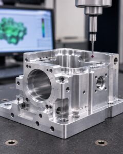
The inspection process typically begins by measuring the datum features and establishing the datum reference frame. The CMM then measures the controlled feature, such as a hole or bore, and calculates the actual position of its centre or axis relative to the theoretically exact location. The result can then be compared with the specified position tolerance. This is particularly useful for complex parts containing multiple holes, bores or geometric relationships.
CMM inspection can also generate clear dimensional reports showing how each feature performed against the drawing requirement. However, measurement strategy still matters. Appropriate points need to be taken, and the component must be supported in a way that does not introduce distortion.
Why Datum Alignment Matters During Inspection
If the datum framework is established incorrectly, the resulting position measurement may not represent the drawing requirement accurately.
This is why inspectors need to understand the datum structure before evaluating the controlled features. For example, if datum A is the primary mounting face, it should establish the first reference plane. Secondary and tertiary datums then complete the coordinate system.
Once this framework is established, the CMM can evaluate the position of the hole or bore relative to the same references defined by the designer. This creates a consistent link between design, machining and inspection.
Common True Position Drawing Mistakes
One common mistake is applying a tight position tolerance without considering whether the datums represent how the part actually assembles.
Another is specifying a tight positional requirement on a hole whose size already provides generous clearance. In that situation, the tolerance may be more restrictive than function requires. Designers may also combine very tight position tolerance with very tight hole size, even though one or both could be relaxed without affecting assembly.
A further issue is inconsistent datum usage across related features. If holes that function together are referenced to different or unrelated datum frameworks, interpreting the actual assembly requirement can become unnecessarily complicated. Good geometric tolerancing should simplify communication, not make it more difficult.
Why Tight Position Tolerances Can Increase Cost
A tighter position tolerance can affect both machining and inspection.
Manufacturing may require more controlled setups, additional finishing operations or greater care in establishing datums. Inspection may also take longer, particularly if every feature needs CMM verification and reporting. This does not mean tight position tolerances should be avoided. Where a feature genuinely needs precise location, the requirement is justified.
The issue is applying a tight tolerance to features where normal clearance or assembly design already provides sufficient flexibility. The closer the tolerance, the more important it becomes to understand what functional problem the requirement is intended to prevent.
Designing Practical Position Tolerances
Before specifying true position, it is worth considering how the feature functions within the final assembly. Useful questions include:
- Does the hole provide clearance or accurate location?
- Is the feature mating with a bolt, dowel, bearing or shaft?
- Which surfaces determine how the component is assembled?
- Are the selected datums genuinely functional?
- Does the feature need position control at MMC?
- Could a slightly larger clearance hole allow a more practical position tolerance?
- How will the feature be inspected?
These questions help ensure that the tolerance supports function rather than simply creating additional manufacturing constraints.
When Should You Discuss True Position With Your CNC Supplier?
Most well-defined positional tolerances can be manufactured directly from a clear drawing, but early discussion can be useful where the component contains very tight true position requirements, several datum references, multiple precision bores, thin walls or complex hole patterns.
The machining supplier may be able to identify a setup or inspection issue before production begins. In some cases, a small change to hole size, datum selection or positional tolerance can simplify manufacture significantly while preserving assembly function. This is particularly useful for repeat components, where even a small improvement in process efficiency can provide benefits across future batches.
True Position and Precision CNC Machining at Tarvin Precision
True position provides a practical way of controlling the location of holes, bores, pins and other features relative to functional datums. By separating theoretically exact position from allowable variation, it can give designers a clearer and more functional way of specifying precision components.
At Tarvin Precision, we manufacture CNC-machined components for demanding engineering applications where positional tolerances, datum structures and controlled inspection may all form part of the drawing requirements.
Where components include tight hole positions, dowel locations, precision bores or other complex geometric relationships, reviewing the drawing before manufacture can help establish an appropriate machining and inspection strategy.
If you have an engineering drawing or CAD model you would like us to review, contact Tarvin Precision to discuss your CNC machining requirements.
Frequently Asked Questions
True position can initially appear complex because it combines datums, basic dimensions, size tolerances and geometric controls. The questions below cover some of the most common points engineers and buyers may encounter when reviewing positional requirements on CNC-machined components.
What does true position mean on an engineering drawing?
True position controls how far the actual location of a feature is allowed to deviate from its theoretically exact position relative to specified datums.
Does true position require datums?
In most practical applications, yes. The datums establish the reference framework from which the exact location of the controlled feature is defined.
What is the difference between true position and hole tolerance?
Hole size tolerance controls the diameter of the hole, while true position controls where the hole is located.
What are basic dimensions in true position?
Basic dimensions define the theoretically exact location of a feature. The allowable variation around that location is controlled by the position tolerance.
What does MMC mean in true position?
MMC means maximum material condition. When used with position tolerance, it can allow additional positional variation as the actual feature moves away from its maximum material size.
How is true position inspected?
True position is commonly inspected using a coordinate measuring machine, which establishes the datum reference frame and measures the actual location of the feature relative to its nominal position.
Can true position apply to bores as well as holes?
Yes. Position tolerance can be used to control holes, bores, pins and other features whose centre or axis must be located accurately.
Does a tighter true position tolerance increase machining cost?
It can. Tighter position requirements may require more controlled setups, more careful datum establishment and additional inspection, particularly where CMM verification is required.