
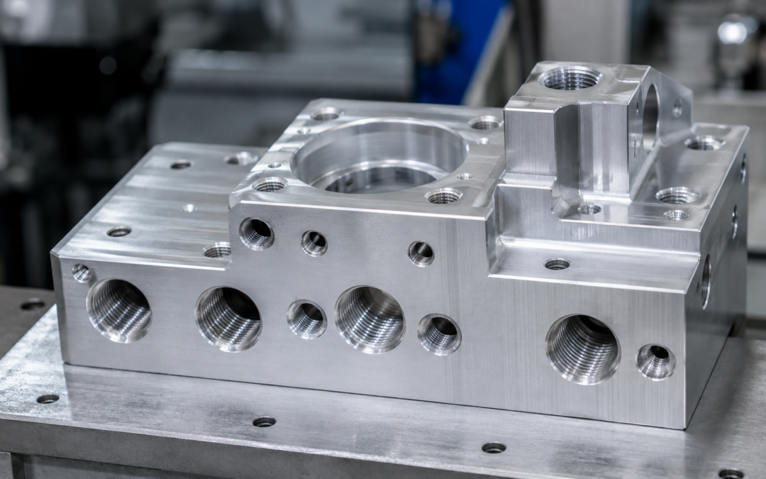
Threaded holes are among the most common features found on CNC-machined components. They may be used to attach covers, secure assemblies, locate brackets, mount electronic equipment or connect one precision-machined part to another.
Although a tapped hole can look straightforward on an engineering drawing, several manufacturing considerations sit behind it. The machinist needs to consider the drilled hole size, thread form, thread depth, available tool access, whether the hole is blind or through, the material being machined and how the finished thread will be inspected.
For designers and buyers, understanding how CNC machined threaded holes are produced can help avoid unnecessary manufacturing difficulty and reduce the risk of ambiguity on engineering drawings. A well-specified threaded feature can often be produced efficiently and repeatedly. A poorly defined one can create questions over usable thread depth, tool clearance, tolerance or whether a mating fastener will actually assemble correctly.
How Are Threads Produced in CNC Machined Components?
There are several methods of producing internal threads in CNC machining. Two of the most common are tapping and thread milling.
Tapping uses a tool with the required thread form already built into it. The tap enters a correctly sized drilled hole and produces the internal thread. Thread milling uses a rotating cutting tool that follows a programmed helical path inside the hole to generate the thread.
Both processes can produce accurate threaded features, but they work differently and may be selected for different applications. Other methods may also be appropriate depending on material, thread size, production volume and component design.
The choice is normally made by the machining supplier based on the requirements of the part. For the designer, the most important point is usually to specify the required thread clearly rather than unnecessarily prescribing the manufacturing method.
What Is a Tapped Hole?
A tapped hole is an internal hole containing a screw thread. The process normally begins by machining or drilling a hole to an appropriate diameter. A tap is then passed through or into the hole to cut the required thread profile.
The starting hole is smaller than the nominal thread diameter because sufficient material must remain for the thread form to be created. For example, an M6 thread does not begin with a 6 mm drilled hole. A smaller tapping-size hole is required. The exact preparation depends on the thread specification and machining process.
For buyers, this distinction is useful because the hole depth and thread depth are not necessarily the same thing. This becomes particularly important with blind tapped holes.
Through Holes Versus Blind Tapped Holes
A through hole passes completely through the material. A blind hole stops inside the component. This apparently simple difference can have a significant effect on threaded-hole design.
With a through tapped hole, the tool can generally continue beyond the threaded section and through the opposite face of the component. A blind tapped hole provides limited space at the bottom. The machinist must therefore allow room for:
- the drilled hole;
- the required usable thread;
- the geometry of the drill point;
- tool approach and clearance;
- the lead or chamfer on the threading tool.
This means a blind hole that requires, for example, 15 mm of full usable thread will normally need to be drilled deeper than 15 mm. If the drawing specifies a hole depth and thread depth without allowing for these factors, the feature may be physically difficult or impossible to manufacture as drawn.
Why Drilled Depth and Usable Thread Depth Differ
This is one of the most useful distinctions for designers to understand. A drill does not normally create a perfectly flat-bottomed hole.
Most standard drills leave a tapered point at the bottom. That pointed area does not provide the same usable cylindrical space as the main body of the hole. The threading tool also needs space. A tap generally has several lead threads at its end that progressively form the thread. These first sections do not immediately create a complete full-depth thread profile. As a result, the total drilled hole accuracy and depth is normally greater than the amount of full usable thread required.
This is why a drawing that simply says “M6 x 15 deep” may require interpretation unless it is clear whether 15 mm refers to thread depth, hole depth or another requirement. Clear specification helps avoid this uncertainty.
Does More Thread Depth Always Make a Joint Stronger?
Not necessarily. Thread engagement is important, but specifying extremely deep threads does not automatically produce a stronger assembly. After a certain amount of engagement, the benefit of additional thread can become limited. The appropriate thread engagement depends on factors such as:
- fastener size;
- fastener material;
- component material;
- applied load;
- type of joint;
- safety requirements.
For many applications, excessively deep threads simply create additional manufacturing work without providing a meaningful functional advantage. They can also require deeper holes, longer tools or increased cycle time. This is particularly relevant in blind holes, where unnecessary depth may create additional machining difficulty.
Thread depth should therefore be based on the engineering requirement of the assembly rather than maximised by default.
Tapping Versus Thread Milling
Tapping and thread milling are both established CNC threading methods. With tapping, the entire thread profile is generated using a tool corresponding to the required thread. This can be an efficient solution, particularly for common thread sizes. 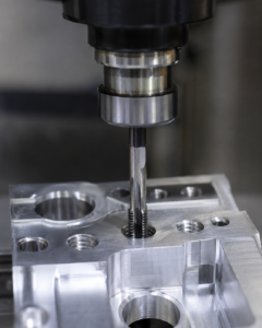
Thread milling takes a different approach. A smaller cutting tool follows a helical interpolation path around the inside of the hole. This creates the thread progressively.
Thread milling can offer advantages in some applications, particularly where thread size, material, hole geometry or process control make it suitable. Depending on the tooling system, one thread mill may also be capable of producing more than one thread diameter with the same pitch. Thread milling can also be useful where chip control or tool-breakage risk needs careful management.
Neither process is universally “better”. The appropriate method depends on the component, thread size, material, quantity and production strategy.
Material Matters When Producing Threads
The workpiece material can significantly influence threading. Aluminium, stainless steel, engineering plastics and other materials all behave differently during machining.
Some materials produce short, manageable chips. Others can create longer or more difficult chips. Material strength also affects the loads experienced by the threading tool. A thread that is straightforward to produce in one material may require a different approach in another.
The component material can also influence thread design from a functional point of view. For example, a threaded hole in a softer material may require different engagement considerations from a similar thread in a stronger material. Where repeated assembly and disassembly is required, the designer may also consider whether a threaded insert is more appropriate.
What Are Thread Inserts?
A thread insert is a separate threaded element fitted into a prepared hole. Various insert systems exist, and they may be used for several reasons.
One common reason is to provide a more durable internal thread in a relatively soft base material. Thread inserts can also be used to repair damaged threads or meet particular design requirements. They are especially familiar in aluminium components that need repeated fastener installation and removal.
Using an insert adds additional manufacturing stages because the component must first be machined to accept the insert, after which the insert is installed. For some applications, however, this extra step can provide a more suitable final assembly. The need for inserts should ideally be considered during the design stage rather than added later unless there is a clear reason.
Metric Thread Specifications
Metric threads are widely used in UK and European engineering. A thread might be specified as:
M6 x 1.0
The “M6” refers to the nominal diameter of the thread.
The “1.0” refers to the thread pitch in millimetres.
For many common metric threads, the standard coarse pitch is widely understood and may not always be shown explicitly. However, where a fine pitch or non-standard requirement is used, clear specification becomes particularly important. Thread designation may also include a tolerance class or other requirements.
The manufacturing supplier needs sufficient information to establish exactly what is required. Ambiguous thread callouts can lead to unnecessary questions during quotation or production.
Coarse Threads Versus Fine Threads
Metric threads are available in both coarse and fine pitches. Coarse threads have a greater distance between adjacent thread peaks. Fine threads have a smaller pitch. Each has different characteristics and potential applications.
A fine-pitch thread provides more threads over a given length and may be useful where adjustment, wall thickness or particular load characteristics are important. Coarse threads are widely used and can offer advantages in general assembly applications.
From a manufacturing perspective, the important consideration is that the required pitch should be clearly identified. A supplier should not be left to guess whether a non-standard or fine-pitch thread was intended.
Thread Tolerances and Fit
Threads have dimensional tolerances just like other machined features. The thread needs to assemble correctly with its mating fastener or component without being excessively tight or loose. Acceptable variation is defined by thread tolerance systems in the finished thread geometry.
For most standard applications, established thread classes provide a practical balance between assembly and manufacturing control. Applying unusually restrictive requirements without a functional reason can increase inspection or manufacturing complexity.
Where a threaded feature is safety-critical or interfaces with specialised equipment, tighter or specific control may be justified. Again, the tolerance should reflect actual function. The aim is not to specify the tightest possible condition, but the correct one.
Thread Inspection in CNC Machining
A finished thread must be checked to confirm that it meets the specified requirement. For many standard internal threads, inspection involves thread plug gauges.
A GO gauge is used to confirm that the thread accepts the required minimum mating condition. A NO-GO gauge is used to confirm that the thread has not exceeded the permitted tolerance condition. This provides a practical method of checking whether the thread is acceptable for assembly. Other measurement or inspection methods may be used depending on the component and specification.
For precision-machined components, thread inspection should form part of the wider inspection process rather than being treated as an isolated feature. Related dimensions such as position, depth and orientation may be equally important to the finished assembly.
Thread Position Can Be as Important as Thread Size
A thread can be manufactured correctly and still create an assembly problem if it is in the wrong position. This is particularly relevant where several threaded holes must align with another component.
Engineering drawings may therefore control not only the thread size but also the positional relationship between threaded features and component datums. The same applies where a tapped hole must align with a clearance hole in another part. CNC machining allows threaded features to be positioned accurately, but this accuracy still depends on clear drawing requirements, suitable datum control and inspection.
This is another reason threaded holes should not be considered purely as individual features. They exist as part of the overall component geometry.
Deep Blind Threads and Tool Access
Deep blind threaded holes can be more challenging than relatively shallow ones. As depth increases, tool access becomes more demanding. Chip evacuation can also become more difficult.
If chips cannot leave the hole effectively, they may interfere with the cutting process or increase tool load. The issue can become more significant in certain materials.
A deep hole may also require longer tooling, which can reduce rigidity. Designers should therefore consider whether the full depth is genuinely required. A long blind tapped hole may look simple in CAD, but the manufacturing process has to create both the drilled feature and the finished thread reliably.
Avoiding Threads Too Close to Other Features
Threaded holes positioned very close to component edges, thin walls or other machined features can create additional manufacturing considerations. If insufficient material surrounds a threaded hole, the thread may not have the strength intended by the designer.
The machining process may also interact with adjacent features. For example, a threaded hole located close to a thin wall may contribute to distortion or create a weak section. Similarly, intersecting drilled holes can influence chip formation and tool behaviour.
These situations are not necessarily impossible to machine, but they should be deliberate design decisions rather than accidental consequences of packaging constraints.
Threads and Surface Treatments
Surface treatments can affect threaded features. Processes such as anodising, plating, painting or other coatings may add material or alter the surface condition. This can influence how a mating fastener fits. Depending on the process and component requirement, threads may need:
- masking;
- allowance for coating thickness;
- post-treatment cleaning;
- chasing or verification after processing.
The appropriate method depends on the coating and thread specification. If a thread must remain free of coating, that requirement should be communicated clearly. Likewise, if the final thread dimension is expected to include the surface treatment, this should be considered during the manufacturing route.
For components that undergo several subcontract finishing processes, the sequence of machining, finishing and final inspection can therefore be important.
Designing Tapped Holes for CNC Machining
Several straightforward design choices can make threaded features easier to manufacture.
Use standard thread sizes where practical.
Common thread sizes usually provide easier access to suitable tooling and gauges.
Avoid unnecessary thread depth.
Specify enough thread engagement for the engineering requirement without adding depth that provides no functional benefit.
Allow sufficient drill depth in blind holes.
Remember that full usable thread does not extend to the very bottom of the drilled hole.
Consider tool access.
Very deep or obstructed threaded holes may require specialised tooling.
Give the thread adequate surrounding material.
Avoid placing threaded holes unnecessarily close to edges or very thin walls.
Clearly define unusual threads.
Fine pitch, left-hand or specialist thread forms should be identified unambiguously.
Consider finishing processes.
If the component will be anodised, plated or painted, define how threaded areas should be treated.
These relatively simple considerations can reduce manufacturing questions later.
What Information Should Be Included on the Drawing?
A well-defined threaded hole should give the manufacturer enough information to understand exactly what is required. Depending on the component, this may include:
- thread size;
- thread pitch;
- tolerance class;
- thread depth;
- whether the feature is through or blind;
- quantity of identical holes;
- hole position;
- surface treatment requirements;
- any special insert specification.
Where a blind hole is involved, the drawing should also distinguish clearly between the required full thread depth and total drilled depth where necessary. Over-specification should be avoided, but ambiguity is equally unhelpful. The best engineering drawings communicate functional requirements clearly while giving the manufacturer reasonable freedom to select the most appropriate machining method.
Can Thread Requirements Affect CNC Machining Cost?
Yes, although standard threaded holes are routine features in precision machining. Cost can increase where the specification introduces additional complexity. Examples include:
- unusually deep blind threads;
- very small threads;
- specialist thread forms;
- fine pitches;
- awkward tool access;
- high quantities of threaded holes;
- thread inserts;
- restrictive tolerances;
- additional inspection requirements.
A component containing twenty tapped holes will naturally involve more machining time than an otherwise identical component containing two. Similarly, a standard through thread is generally less complex than a deep blind thread located at the bottom of an awkward pocket. Looking at threaded features during design for manufacture can therefore help identify relatively simple opportunities to control machining time.
When Should You Discuss Threads With Your CNC Machining Supplier?
Most common threaded features can be quoted directly from a clear engineering drawing. Discussion becomes particularly useful where a component contains:
- deep blind threads;
- very small threads;
- unusual pitches;
- specialist thread forms;
- thread inserts;
- threads close to thin walls;
- restricted cutter access;
- significant finishing or coating requirements.
Early discussion can help confirm that the thread is practical and that the drawing communicates the intended function clearly. In some cases, a small adjustment to depth, position or surrounding geometry can simplify manufacture without affecting the finished assembly.
CNC Machined Threaded Components at Tarvin Precision
Tapped holes and other threaded features are routine parts of many precision CNC-machined components, but producing them consistently still requires appropriate tooling, process control and inspection.
At Tarvin Precision, we manufacture CNC-machined components incorporating threaded holes, bores, pockets and other detailed features for customers across demanding engineering applications. Where components contain unusual thread requirements, deep blind holes, tight positional CNC machining tolerances or additional finishing processes, considering these factors early can help establish a reliable manufacturing route.
If you have an engineering drawing or CAD model containing threaded features that you would like us to review, contact Tarvin Precision to discuss your requirements.
Frequently Asked Questions
These are the FAQs about tapped holes in CNC machined parts that we hear.
What is a tapped hole in CNC machining?
A tapped hole is an internal hole containing a screw thread. The hole is first produced to an appropriate size, after which the thread is created using a tap or another threading process.
What is the difference between a blind tapped hole and a through tapped hole?
A through tapped hole passes completely through the component. A blind tapped hole stops within the material, meaning additional consideration must be given to CNC drilling tools depth, tool clearance and usable thread depth.
Why does a tapped hole need to be drilled deeper than the required thread depth?
The bottom of a drilled hole usually includes the tapered drill point, while the end of a tap may contain lead threads that do not produce a complete thread profile. Additional hole depth is therefore normally required to achieve the specified length of usable full thread.
What is thread milling?
Thread milling is a CNC machining process in which a cutting tool follows a helical path inside a hole to generate the thread. It differs from tapping, where a tool containing the complete thread form is fed into the prepared hole.
Are deeper threads stronger?
Not indefinitely. Additional thread engagement can improve joint strength up to a point, but excessively deep threads may add machining time without producing a meaningful functional benefit. The appropriate engagement depends on the materials, fastener and load.
How are internal threads inspected?
Standard internal threads are commonly checked using GO and NO-GO thread plug gauges. Additional dimensional or positional inspection may also be required depending on the engineering drawing.
Can anodising or coating affect threaded holes?
Yes. Surface treatments may alter thread dimensions or deposit material within the thread. Threads may therefore require masking, allowance for coating thickness or inspection after finishing, depending on the process and component specification.