
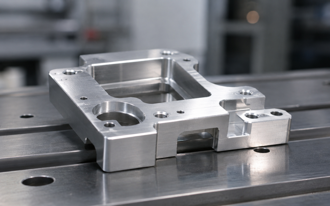
“Break all sharp edges” is one of those engineering drawing instructions that appears simple until someone has to decide exactly what it means.
For a CNC machining supplier, the intention is usually clear: finished components should not be supplied with unwanted burrs or dangerously sharp edges created during machining.
The difficulty is that the instruction does not necessarily define exactly how much material should be removed. Should an edge receive the lightest possible deburr? Should it have a visible chamfer? Does the requirement apply to every internal and external edge? What happens if a sharp edge is functionally important to the component? Understanding the break all sharp edges meaning is therefore useful for designers, engineers and buyers specifying CNC-machined components.
Edge condition can affect safety, assembly, appearance, coating, inspection and component function. Although deburring is often one of the final stages of manufacture, it should not necessarily be treated as an afterthought.
What Does “Break All Sharp Edges” Mean?
On an engineering drawing, “break all sharp edges” generally instructs the manufacturer to remove sharp corners and burrs left by the machining process.
The objective is normally to leave the component safe to handle and suitable for its intended use without materially altering the specified geometry. Breaking an edge usually means removing only a small amount of material. This may be achieved by:
- light manual deburring;
- creating a small chamfer;
- applying a small radius;
- using mechanical deburring equipment;
- including an edge-breaking operation within the CNC machining process.
The exact method depends on the part. Importantly, “break all sharp edges” does not necessarily mean that every edge should receive a large visible chamfer. Where the size of the edge break is functionally important, it is better to define it explicitly on the drawing.
Why Does CNC Machining Create Sharp Edges?
CNC milling and turning processes remove material by cutting. Where two machined surfaces meet, the resulting intersection can be very sharp. Machining operations may also leave small burrs along an edge. A burr is unwanted material that remains attached to the component after cutting.
The amount and type of burr can depend on:
- workpiece material;
- cutting tool;
- tool condition;
- feed and speed;
- direction of cutting;
- geometry of the component;
- machining process.
Some materials are more prone to producing noticeable burrs than others. Even where a CNC machine has produced every specified dimension correctly, a component may still require finishing to remove these unwanted sharp edges. This is why deburring is a normal part of many machining processes rather than a correction for inaccurate machining.
What Is Deburring?
Deburring is the process of removing burrs created during manufacture. The objective is generally to remove unwanted projections without damaging the intended component geometry.
Depending on the component, deburring may be carried out manually or mechanically. Typical methods can include abrasive tools, hand tools, brushes or dedicated deburring equipment. Some edges may also be chamfered directly during CNC machining. The appropriate technique depends on factors including:
- component size;
- material;
- geometry;
- tolerance;
- edge accessibility;
- production quantity;
- surface finish requirements.
A simple component may take very little time to deburr. A complex component containing many holes, pockets and intersecting features can require considerably more attention.
Deburring Versus Breaking an Edge
The terms are closely related but do not always mean exactly the same thing.
Deburring focuses on removing unwanted material produced by the manufacturing process.
Breaking an edge intentionally removes the sharp intersection between two surfaces.
A component could theoretically be free from burrs while still having an extremely sharp machined corner. Similarly, creating a small chamfer may both break the sharp edge and remove any burr present.
On many engineering drawings, phrases such as “deburr and break all sharp edges” are used together to communicate the required final condition. Where edge geometry matters, however, relying only on a general note can create uncertainty. A defined chamfer or radius is normally preferable when its dimensions are functionally significant.
Chamfers Versus Radiused Edges
There are two common ways of intentionally removing a sharp corner: a chamfer or a radius. 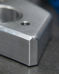
A chamfer creates a flat angled surface between two adjoining faces.
A radius creates a curved transition.
For example, an external edge might be specified with a 0.5 mm x 45° chamfer. Alternatively, it could have a 0.5 mm radius. These two edge conditions are visibly and geometrically different.
If the requirement is only to remove sharpness for handling, the exact form may not always matter. However, where the edge forms part of an interface, controls airflow, affects sealing or has an appearance requirement, the designer should specify the intended geometry.
The phrase “break sharp edge” should not be used as a substitute for a defined chamfer where that chamfer is important to function.
How Much Material Should Be Removed?
This is where general drawing notes can become ambiguous. “Break all sharp edges” does not, by itself, always define the maximum amount of material that may be removed.
One machinist might interpret it as the lightest possible deburr. Another might apply a small but clearly visible edge break. In many applications, this variation has no functional effect. In others, removing too much material could affect:
- mating geometry;
- sealing surfaces;
- wall thickness;
- hole entrances;
- datum features;
- cosmetic appearance.
Where the permitted edge break has limits, the drawing should communicate them. For example, a general note might define a maximum chamfer for unspecified edges or internal hole radii, giving the machining supplier an objective requirement and making inspection easier.
Can Every Sharp Edge Simply Be Removed?
No. Some sharp edges are intentional. A component may contain a feature where a crisp edge is required for function. Examples could include:
- locating features;
- sealing interfaces;
- metrology surfaces;
- cutting or scraping features;
- defined contact points;
- certain mating geometries.
Applying a general edge-breaking instruction blindly to these areas could change the component function. This is why the drawing should make clear where exceptions apply. If an edge must remain sharp, it can be identified specifically rather than relying on the manufacturer to infer its importance.
The same principle applies in reverse: if an edge needs a particular chamfer or radius, define it rather than leaving it to a general note.
Internal Edges Can Be More Difficult to Deburr
External edges are often relatively easy to access. Internal edges can be more challenging. Examples include:
- intersections between drilled holes;
- deep pockets;
- cross-holes;
- narrow slots;
- internal bores;
- recessed features.
A burr located deep inside a component may require different tooling or additional operations to remove. Cross-drilled precision holes are a good example. When one drilled hole breaks into another, a burr may be created at the internal intersection. The outside of the component may look completely finished while unwanted material remains internally.
For components carrying fluid, gas, wiring or sensitive mechanisms, internal burrs may be particularly undesirable. Designers should therefore consider whether general external deburring is sufficient or whether internal edge condition needs additional attention.
Why Cross-Holes Require Care
Intersecting drilled holes appear in many machined components, including manifolds and fluid-control parts.
When a drill passes through into another bore, material can be pushed or torn around the exit point. This can leave an internal burr. Because the feature may be inaccessible to conventional hand tools, removal can require specialist techniques or dedicated tooling.
If internal cleanliness or unrestricted flow is important, the drawing may need to state the requirement explicitly. A general “break all sharp edges” note may not fully communicate the significance of a particular internal intersection.
This is another example of why the function of the edge matters as much as the instruction itself.
Edge Breaking Around Holes
Drilled and machined holes often have their edges broken. A small chamfer at the entrance of a hole can provide several benefits. It can:
- remove burrs;
- make assembly easier;
- help locate a fastener or pin;
- improve handling;
- reduce the risk of damaging mating components.
However, the chamfer size should still reflect function. A large chamfer around a precision bore could reduce the available bearing or locating surface. Similarly, excessive material removal around CNC machined threaded holes may alter how a fastener seats. Where a specific lead-in or countersink is required, it should be called out separately rather than being left under a general edge-breaking instruction.
Edge Conditions on Thin-Walled Parts
Thin-walled components require additional care during deburring. The edge itself may have relatively little supporting material.
Aggressive manual finishing can therefore damage or distort the feature. Removing too much material can also reduce wall thickness locally. For delicate parts like thin-walled components, deburring methods may need to be selected carefully to avoid affecting dimensional accuracy. This is another reason edge finishing should form part of the overall manufacturing plan.
The machining supplier needs to consider not only how to cut the thin section accurately, but how to finish and inspect it afterwards without introducing new problems.
Manual Deburring
Manual deburring remains useful for many precision components. An experienced operator can selectively remove burrs and break individual edges using suitable hand tools.
The advantage is flexibility. The operator can adapt the method to different areas of a complex CNC machining component. However, manual operations naturally involve an element of judgement. If the drawing does not define the required edge condition clearly, the exact result may vary slightly. For non-critical edges this may be perfectly acceptable.
Where consistent edge geometry is required across a production batch, machining a defined chamfer directly on the CNC machine may offer greater repeatability. The decision depends on the component and the level of control required.
Machine-Chamfering Edges
Many edge breaks can be incorporated directly into the CNC machining programme. A chamfer tool can follow the required edges and create a controlled chamfer. This can offer benefits in consistency and repeatability. It may also reduce the amount of manual finishing required.
However, not every edge is accessible to a CNC chamfering tool. Complex internal intersections or obstructed features may still require a different approach.
There is also a difference between machining a specified chamfer and simply deburring a component. If a drawing explicitly requires a defined chamfer, producing that geometry on the CNC machine may be the most appropriate method. If the requirement is simply “no sharp edges”, a lighter finishing process may be sufficient.
Why Edge Requirements Can Affect Cost
Deburring is sometimes treated as a negligible part of machining. For simple components, it may represent only a small proportion of overall production time. For complex parts, however, edge finishing can become significant. Consider a component containing:
- dozens of holes;
- multiple pockets;
- intersecting bores;
- narrow slots;
- numerous internal and external edges.
Each feature may need inspection and finishing. If the component also requires a controlled chamfer on every edge, additional CNC programming and cycle time may be involved.
Edge requirements can therefore influence cost, particularly in higher quantities where finishing time is repeated across every part. This does not mean edge breaking should be avoided. It simply means that edge condition is a genuine manufacturing requirement and should be specified according to function.
Deburring Before Surface Treatment
Many CNC-machined components undergo additional processes after machining. These can include:
- anodising;
- plating;
- painting;
- conversion coating;
- other protective finishes.
Deburring would normally need to be considered before these processes. A burr that remains on the component may receive the coating along with the rest of the surface. If it is removed afterwards, the newly exposed area may no longer have the intended surface treatment. Sharp edges can also behave differently during some coating processes.
The complete manufacturing route should therefore consider machining, edge finishing and surface treatment in the correct sequence. For demanding components, final inspection may take place after finishing to ensure both geometry and surface condition remain acceptable.
Edge Breaking and Aerospace Components
In aerospace and other tightly controlled engineering sectors, component finishing and documentation can be particularly important. A machined part may have detailed drawing notes defining burr removal, edge condition, surface treatment and inspection requirements.
These requirements form part of the controlled manufacturing process. It is not sufficient to assume that a component is acceptable simply because its main dimensions are within tolerance. Surface condition, edge quality and the absence of unwanted burrs may all contribute to conformity. This is one reason experienced suppliers of CNC machining services pay close attention to drawing notes as well as dimensional callouts.
Inspection of Edge Condition
Edge condition can be inspected visually or using measurement equipment, depending on the requirement. Where the instruction is simply to remove burrs and sharp edges, visual and tactile checks may be appropriate. Where a chamfer or radius is dimensioned, it becomes a measurable feature. Inspection methods can include:
- visual inspection;
- magnification;
- chamfer gauges;
- optical measurement;
- profile measurement;
- coordinate measurement where appropriate.
The more precisely the edge geometry is defined, the more objectively it can be inspected. This is one reason vague instructions should generally be reserved for genuinely non-critical edges. If the customer needs a specific result, the drawing should provide a measurable requirement.
How Should “Break All Sharp Edges” Be Specified?
There is no universal wording appropriate for every engineering drawing. A general note may be perfectly suitable for a component where edge geometry is non-critical. For example, the intention may simply be to remove all burrs and leave the component safe to handle.
Where tighter control is required, the drawing can define the permissible edge condition more precisely. The key questions are:
Is a particular chamfer or radius required?
If yes, dimension it.
Is the exact geometry unimportant as long as the edge is not sharp?
A general edge-breaking note may be appropriate.
Are there edges that must remain sharp?
Identify those as exceptions.
Are difficult internal burrs important to function?
Call out those areas if necessary.
Does the surface treatment impose additional requirements?
Ensure the edge condition is compatible with the finishing process.
The objective should be clarity without unnecessary over-specification.
Avoiding Ambiguity on Engineering Drawings
Good engineering drawings tell the supplier what the finished component must do without unnecessarily dictating every detail of how it should be manufactured. A general note such as “deburr all edges” can work well where the edge condition is non-critical.
Problems arise when a designer expects a very specific chamfer but only provides a general deburring instruction. The manufacturer cannot reliably infer a requirement that is not shown.
Similarly, specifying tiny chamfers on every edge simply because the CAD system makes it easy to add them can increase drawing complexity and machining time. Design intent should drive the specification. For each edge, ask whether the exact geometry matters. If it does, define it. If it does not, allow the machining supplier reasonable flexibility.
What Should Buyers Check on a Machined Component?
When receiving CNC-machined components, buyers and inspectors may want to look beyond the main dimensions. Depending on the drawing, useful checks can include:
- absence of loose burrs;
- absence of dangerous sharp edges;
- consistency of specified chamfers;
- clean hole entrances;
- condition of cross-hole intersections;
- damage from excessive deburring;
- conformity of edges after coating or finishing.
A good finished component should show evidence of controlled manufacture, not simply material removal. Edge quality is one of the small details that can strongly influence the overall impression of workmanship.
When Should You Discuss Edge Requirements With Your CNC Supplier?
Most ordinary deburring requirements do not require lengthy discussion. It becomes useful to involve the machining supplier where the component includes:
- difficult internal intersections;
- very small or fragile features;
- thin walls;
- critical sealing edges;
- tightly controlled chamfers;
- unusual cosmetic requirements;
- complex coating or finishing processes;
- edges that must remain intentionally sharp.
In these situations, clarifying the requirement before machining begins can prevent disagreement later about what constitutes an acceptable finished edge.
Deburring and Edge Finishing at Tarvin Precision
“Break all sharp edges” may be a short drawing note, but producing the correct finished condition still depends on understanding the component, its geometry and its function. At Tarvin Precision, finishing and inspection form part of the overall CNC machining process.
Components may contain machined pockets, drilled holes, threads, internal features, tight CNC machining tolerances and surface-finishing requirements, all of which need to be considered as part of a controlled manufacturing route.
Where an engineering drawing contains unusual edge requirements, difficult internal burr locations or defined chamfers, reviewing those features before production can help ensure the manufacturing and inspection approach reflects the design intent.
If you have a component drawing or CAD model that you would like us to review, contact Tarvin Precision to discuss your CNC machining requirements.
Frequently Asked Questions
Here are the FAQs we hear most often in relation to this notation on an engineering drawing.
What does “break all sharp edges” mean on an engineering drawing?
It generally means removing burrs and sharp machined corners so the component is safe to handle and suitable for use. Unless a specific size is stated, the instruction may not define an exact chamfer or radius.
Is breaking an edge the same as deburring?
Not exactly. Deburring removes unwanted material created during machining. Breaking an edge intentionally removes the sharp intersection between two surfaces. A single finishing operation may achieve both.
How are sharp edges removed from CNC-machined parts?
Methods can include manual deburring, abrasive finishing, brushing, specialist deburring equipment or machining a chamfer directly using a CNC cutting tool.
Does “break all sharp edges” mean adding a chamfer?
Not necessarily. A light radius or minimal deburr may satisfy the requirement where no specific geometry is defined. If a particular chamfer is required, it should normally be dimensioned on the drawing.
Should all edges on a CNC-machined component be deburred?
Unwanted burrs would normally be removed, but some sharp edges may be functionally important. Any edge that must remain sharp should be identified appropriately on the engineering drawing.
Why are internal burrs difficult to remove?
Internal burrs may occur at cross-holes, deep pockets or other inaccessible intersections. Because conventional hand tools cannot always reach these areas, additional or specialised deburring methods may be required.
Can deburring affect dimensional tolerances?
Yes, if too much material is removed. This can be particularly important around thin walls, precision bores, datum surfaces or other tightly controlled features. Deburring should remove unwanted material without altering the functional geometry of the component.