
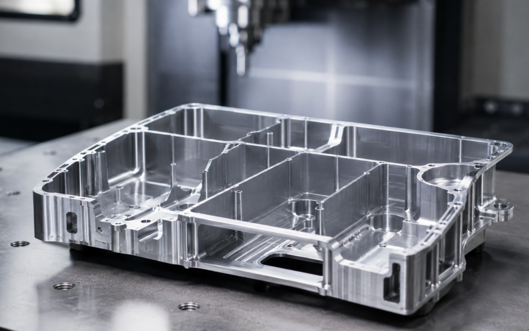
Thin-walled components can look relatively straightforward on an engineering drawing. In practice, however, removing material from a component until only thin sections remain can create some of the more challenging conditions encountered in precision CNC machining.
As wall thickness reduces, the component becomes less rigid. Cutting forces, workholding pressure, heat and stresses within the material can all influence its final shape. A feature that is within tolerance while held securely on the machine may move slightly once the component is released.
Successful thin wall CNC machining therefore depends on much more than simply achieving the programmed dimensions. Tool selection, machining sequence, workholding, cutting strategy and inspection all need to be considered together. For designers and buyers of precision-machined components, understanding these factors can help avoid unnecessarily difficult features and improve discussions with the machining supplier before production begins.
What Is a Thin-Walled Machined Component?
There is no single wall thickness at which a component automatically becomes a “thin-wall” machining job.
Whether a section behaves as a thin wall depends on factors including its height, length, geometry, material, surrounding support and the machining operation being carried out. A relatively short wall may remain rigid even when it is quite thin. A much taller or longer section of the same thickness may flex considerably more easily. Thin sections can occur in components such as:
- housings and enclosures;
- aerospace components;
- electronic and scientific instrument parts;
- lightweight structural components;
- brackets;
- covers;
- manifolds;
- pockets with thin dividing walls;
- instrument components;
- prototypes where weight or available space is restricted.
Aluminium is commonly associated with thin-walled machining because it combines relatively low weight with good machinability. However, thin sections can also be encountered when machining stainless steels, engineering plastics and many other materials. The important question is not simply “how thin is the wall?” but how stable will the component remain while material is being removed?
Why Are Thin Walls Difficult to CNC Machine?
A solid block of material provides considerable resistance to cutting forces. As material is progressively removed, that rigidity reduces. When a cutting tool contacts a thin wall, the wall itself can begin to behave almost like a spring. Rather than remaining completely stationary, it can deflect away from the cutter and then return towards its original position after the tool has passed. This can affect:
- wall thickness;
- dimensional accuracy;
- straightness;
- flatness;
- surface finish;
- positional accuracy of related features.
The challenge can become greater when a wall is both thin and tall, or when a large pocket leaves relatively little supporting material around it. Machining strategy consequently becomes increasingly important as the component approaches its finished geometry. A toolpath that works perfectly well during rough machining may not be appropriate when only a slender wall remains.
How Cutting Forces Can Cause Thin-Wall Distortion
Every machining operation introduces forces into the workpiece. When the workpiece is sufficiently rigid, these forces normally have little noticeable effect on its geometry. With a thin section, the same forces may cause temporary deflection.
Imagine machining along the side of a tall, thin aluminium wall. Pressure from the cutting tool may push the wall slightly away from its intended position. The machine itself is following the programmed toolpath accurately, but the material being cut is moving. Once the cutter moves away, the wall can spring back. The result may be variation in wall thickness or a surface that does not exactly correspond with the programmed geometry.
Managing this often means reducing the forces applied during the finishing stages. Possible approaches include appropriate tool selection, lighter cuts and machining strategies designed to reduce engagement between the cutter and workpiece. It is therefore important to distinguish between machine accuracy and component behaviour. A highly accurate CNC machine cannot, on its own, prevent a flexible component from moving during machining.
Workholding Thin-Walled Components
Secure workholding is essential in CNC machining, but more clamping force is not necessarily better.
Applying excessive pressure to a relatively flexible component can distort it before machining even begins. The machine may then produce features accurately while the part is being held in its distorted state. When the clamps are released, the component can move back towards its natural shape and the dimensions may change.
This is one reason workholding needs careful consideration for CNC machining thin-walled components. Depending on the geometry, possible approaches can include:
- supporting the component close to the area being machined;
- spreading clamping forces across a larger area;
- using soft jaws designed for the component;
- machining purpose-made fixtures;
- using existing rigid sections of the component for location;
- planning operations so rigid material remains available for workholding for as long as possible.
There is no universal fixture for thin-wall machining. The most suitable solution depends heavily on the individual part. For complex CNC machining or repeat-production components, the design and manufacture of appropriate workholding can be an important part of the overall manufacturing process.
Machining Sequence Matters
The order in which material is removed can have a major effect on component stability. One of the risks when machining a thin-walled part is removing supporting material too early.
If a wall is finished to its final thickness while substantial machining is still required elsewhere, it may have to withstand cutting forces from subsequent operations despite having very little rigidity. A more controlled approach can be to leave additional material on vulnerable features during earlier stages. For example, the machining process might involve:
- removing the majority of unwanted material;
- establishing important datum features;
- leaving thin sections slightly oversize;
- completing other machining while the component remains relatively rigid;
- progressively finishing the thin walls later in the process.
This principle is sometimes more important than simply reducing cutting speed. The objective is to maintain as much useful support within the component as possible while the heavier material-removal operations are completed.
Roughing and Finishing Thin Sections
Separating roughing from finishing is particularly useful in thin-wall machining.
During roughing, the priority is generally efficient material removal while keeping sufficient stock for subsequent operations. Finishing has a different purpose. At this point the focus shifts towards dimensional accuracy, surface condition and final geometry.
Trying to remove a significant amount of material from a thin wall during the final pass can increase the forces acting on the feature. Instead, a controlled amount of material can be left for finishing so that the final operation requires relatively little cutting force.
In some situations, material may also be removed progressively from both sides of a wall rather than completely finishing one side while substantial stock remains on the other. The optimum strategy depends on the geometry, but the general principle is straightforward:
as the component becomes less rigid, the machining process should become progressively more controlled.
Tool Selection for Thin Wall CNC Machining
Tool selection can influence both cutting force and vibration. A cutter must be capable of reaching the required geometry, but unnecessary tool length should generally be avoided where possible. Increasing tool overhang reduces tool rigidity and can introduce another source of deflection into a process already involving a relatively flexible component.
Tool diameter, flute geometry, condition and cutting edge also matter. The objective is usually to achieve efficient cutting rather than forcing or rubbing against the material. A suitable cutting tool combined with appropriate machining parameters can help reduce the load transferred into the thin section.
This highlights an important aspect of precision machining: simply selecting the smallest cutter that physically fits a feature is not always the most effective manufacturing approach. Design features such as deep pockets, precision holes, narrow slots and very small internal corner radii can require long, slender tooling. When those features are combined with thin walls, manufacturing becomes considerably more demanding.
Design for manufacture should therefore consider the relationship between wall thickness, feature depth and cutter access, rather than treating each dimension independently.
Internal Corner Radii Can Affect Thin-Wall Machining
Internal corner radii are particularly relevant where thin walls form the sides of deep pockets. CNC milling cutters are round, which means milled internal corners naturally contain a radius.
Specifying an unnecessarily small radius can require a smaller-diameter cutter. If the pocket is also deep, that cutter may need significant reach. The combination of a long cutter, thin wall and deep pocket can create an unnecessarily difficult machining condition. Where the component design allows it, increasing the internal corner radius can permit the use of a larger and more rigid cutting tool. This can potentially improve:
- machining stability;
- tool life;
- surface finish;
- material-removal efficiency;
- consistency.
It can also help reduce machining time. This is a useful example of why seemingly minor drawing decisions can have consequences for manufacturability and cost.
Residual Stress and Material Movement
Not all machining distortion is caused directly by cutting forces or workholding. Material itself can contain residual stresses resulting from processes used during its manufacture.
As material is removed, the balance of those internal stresses can change. A component that began as a flat piece of material may consequently move as machining progresses. The effect can be especially noticeable where a large proportion of the original stock is removed to leave a relatively lightweight finished component. Machining strategy can help manage this risk. Depending on the component, a machinist may remove material in stages or use an approach intended to keep material removal more balanced.
Material condition and stock selection can also form part of the planning process for particularly demanding components. This is one reason thin-wall machining should not be viewed solely as an exercise in programming nominal dimensions. The physical behaviour of the material throughout manufacture matters too.
Heat and Machining Stability
Machining generates heat, although the amount transferred into the component varies greatly according to material, tooling and cutting conditions.
Where geometry is delicate, maintaining a stable machining process becomes especially important. Appropriate tooling, cutting parameters and coolant application can help control the cutting process and evacuate chips effectively. Chip evacuation itself should not be overlooked. Recutting chips or allowing material to accumulate around a delicate feature can affect surface finish and machining consistency.
Again, thin-wall machining tends to reward a controlled process in which several relatively small factors work together rather than relying on one individual technique.
Inspection of Thin-Walled Components
Inspecting a flexible component can present some of the same challenges as machining it. If excessive force is applied during measurement, the inspection process itself can influence the component. 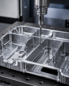
The appropriate inspection method will depend on the feature and tolerance being assessed. Equipment may include:
- micrometers;
- vernier or digital measuring equipment;
- bore measurement equipment;
- height gauges;
- surface tables;
- coordinate measuring machines (CMMs);
- dedicated gauges or fixtures.
It is also important to consider what the drawing is actually controlling. Wall thickness is only one potential requirement. A thin component might also have tolerances relating to:
- flatness;
- perpendicularity;
- parallelism;
- profile;
- true position;
- bore alignment.
For demanding components, inspection planning should therefore form part of the manufacturing approach rather than being treated purely as a final check after machining has been completed.
Avoiding Unnecessarily Tight Tolerances
One of the most useful things a designer can do is apply tolerances according to functional requirements.
A very tight tolerance may be essential for an interface, bearing location, seal or mating feature. Applying the same level of control to every dimension on a thin-walled component can add manufacturing difficulty without improving its function. This does not mean thin components cannot be manufactured accurately. It means the relationship between tolerance, geometry and function should be considered carefully. Features that combine several challenging characteristics can be particularly significant. For example:
- a very thin wall;
- substantial wall height;
- a deep pocket;
- small internal corner radii;
- a tight dimensional tolerance;
- demanding geometric control.
Any one of these requirements may be manageable. Combining all of them into the same feature can make the machining process significantly more complex. Early discussion between designer and machining supplier can help identify where a small design adjustment might simplify production without affecting performance.
Designing Thin-Walled Parts for CNC Machining
There is rarely a single design rule that applies to every thin-walled component, but several questions are worth considering during the design stage.
Does the wall genuinely need to be this thin?
If additional thickness would have no effect on function, leaving more material can increase rigidity and simplify machining.
Is the wall consistently supported?
Long unsupported sections are generally more susceptible to movement than short or well-supported features.
Are the internal radii unnecessarily small?
Allowing larger cutter radii where possible may enable more rigid tooling.
Are deep features combined with thin walls?
Depth can increase tooling reach and reduce machining rigidity.
Are tolerances being applied according to function?
Critical interfaces may justify tight control, while non-critical surfaces may not.
Can the component be held securely?
Workholding needs are worth considering before the design is finalised, particularly for components requiring machining on several faces.
These are exactly the kinds of issues that can be addressed through early design-for-manufacture discussions.
When Should You Discuss Thin Walls With Your CNC Machining Supplier?
If a design contains substantial pockets, lightweight structures, deep cavities or thin unsupported sections, it can be useful to involve the machining supplier before manufacture begins.
A machinist looking at the drawing may identify issues that are not immediately obvious from the CAD model alone. These might include tooling access, difficult workholding locations, areas vulnerable to deflection or a tolerance that could be achieved more efficiently with a minor design change.
This does not necessarily mean redesigning the component. Often, the value of the conversation is simply confirming that the required geometry is practical and agreeing an appropriate manufacturing route before material and machining time are committed. For repeat components in particular, a well-planned process can also improve consistency from batch to batch.
Thin-Wall CNC Machining at Tarvin Precision
Thin-walled components demonstrate why precision CNC machining involves more than programming a toolpath and pressing cycle start. Component geometry, workholding, cutter selection, material behaviour, machining sequence and inspection all influence the finished result.
At Tarvin Precision, we manufacture CNC machined components for customers requiring controlled, repeatable precision engineering across a range of demanding applications. Where a component contains thin sections, deep pockets, critical CNC machining tolerances or other challenging features, reviewing manufacturability before production can help establish an appropriate machining and inspection strategy.
If you have a component drawing or CAD model that you would like us to review, contact Tarvin Precision to discuss your requirements.
Frequently Asked Questions
Here are some of the FAQs about thin wall CNC machining that we hear.
What is thin wall CNC machining?
Thin wall CNC machining describes the manufacture of components containing relatively slender or flexible sections. As material is removed, these areas can become more susceptible to cutting forces, workholding pressure, vibration and material movement, requiring careful control of the machining process.
Why do thin-walled parts distort during machining?
Distortion can result from several factors, including cutting forces, clamping pressure, heat and residual stresses within the raw material. Removing material also reduces component rigidity, making remaining sections more likely to move.
Can aluminium thin-walled components be CNC machined accurately?
Yes. Aluminium is widely used for lightweight precision-machined components. Achieving the required accuracy depends on factors such as component geometry, wall thickness, tooling, workholding, machining sequence and the tolerances specified on the drawing.
How can CNC machining distortion be reduced?
There is no single solution. Techniques can include maintaining supporting material until later operations, controlling cutting forces, using appropriate tooling, avoiding excessive clamping pressure, planning the machining sequence carefully and using suitable inspection methods.
Why is workholding important when machining thin walls?
A flexible component can be distorted by excessive clamping force. If machining takes place while the part is distorted, dimensions can change when the component is released from the fixture. Workholding therefore needs to secure the part without unnecessarily deforming it.
Do thin walls make CNC-machined components more expensive?
Not automatically. However, very thin sections combined with deep features, difficult workholding or tight tolerances can require additional machining time, specialist fixtures, lighter finishing cuts or more inspection. Considering manufacturability during the design stage can help control these costs.