
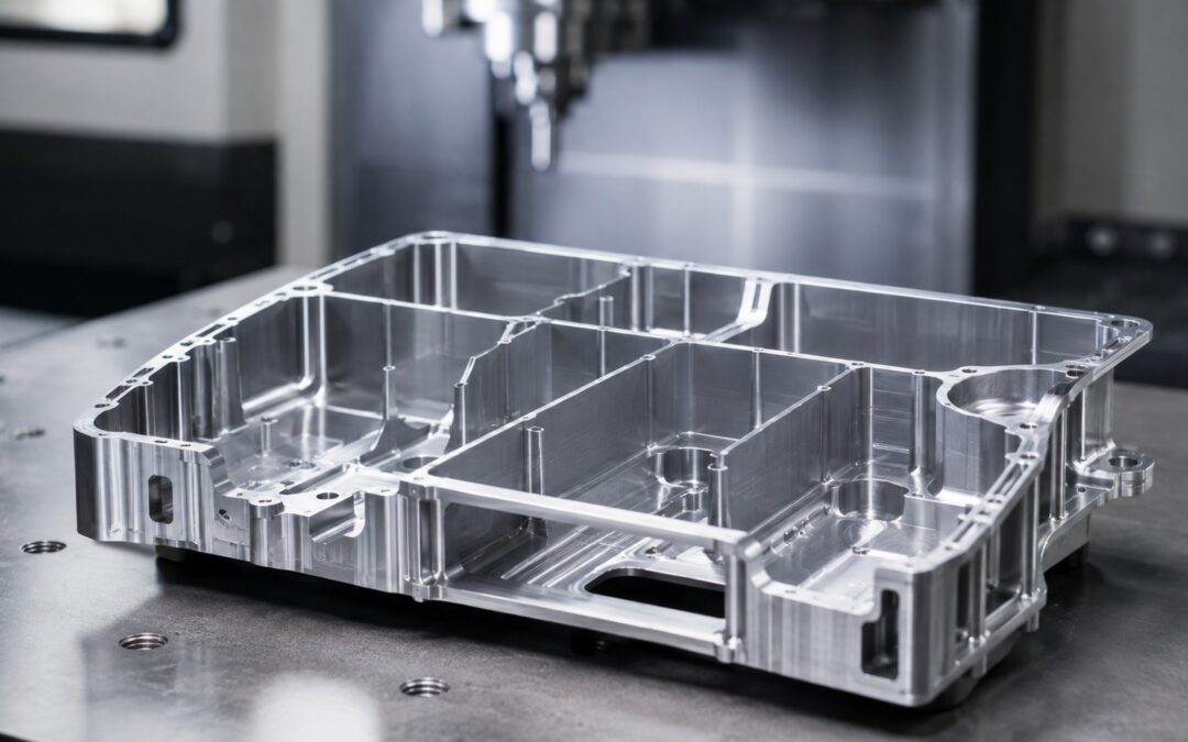
Flatness and parallelism are two common geometric tolerances used on engineering drawings, and although they can look similar at first glance, they control different characteristics of a machined component. Flatness controls the form of an individual surface, while parallelism controls the orientation of a surface or feature relative to a specified datum.
Understanding flatness vs parallelism is important because a surface can be very flat without being parallel to another surface. Equally, a component can satisfy a dimensional thickness requirement while still having surfaces that do not meet the required geometric relationship.
For designers, buyers and engineers sourcing precision CNC-machined parts, selecting the correct tolerance helps ensure that the drawing communicates what the component actually needs to do. It also allows the machining supplier to plan the manufacturing and inspection process around the functional requirement rather than trying to interpret an unnecessarily restrictive or ambiguous specification.
What Is Flatness?
Flatness is a geometric form tolerance that controls how closely a surface conforms to an ideal plane. In simple terms, it defines how much variation is allowed across the entire surface.
The controlled surface must remain between two imaginary parallel planes separated by the specified flatness tolerance. If any part of the surface falls outside this zone, the feature does not meet the requirement.
One of the most important characteristics of flatness is that it does not require a datum. The surface is assessed independently rather than being compared with another part of the component. This makes flatness useful for features such as mounting faces, sealing surfaces, machine bases, covers and precision plates where the primary concern is that the surface itself does not contain excessive bow, twist or waviness.
For example, a large mounting face may need to sit securely against another component. If the surface is significantly bowed, the part may rock, create uneven contact or introduce unwanted stress into the assembly when fasteners are tightened. A flatness tolerance provides a clear way of controlling this condition.
What Is Parallelism?
Parallelism is an orientation tolerance. Rather than controlling a surface independently, it controls how that surface or feature is orientated relative to a datum. A datum is therefore required.
Imagine a CNC-machined housing with a lower mounting surface identified as datum A. If an upper machined face needs to remain parallel to that mounting surface, the drawing can specify a parallelism tolerance relative to datum A. The controlled surface must then remain within an allowable tolerance zone that is oriented parallel to the datum.
This is particularly useful where the relationship between two features affects assembly or function. Examples can include opposing mounting faces, bearing locations, fixture surfaces, precision spacers or components that stack together.
The key point is that parallelism is not simply asking whether the controlled surface is flat. It is asking whether that surface remains correctly orientated relative to another defined feature.
Flatness vs Parallelism: The Main Difference
The easiest way to distinguish the two is to think of flatness as controlling shape, while parallelism controls orientation. A surface can therefore be perfectly flat but still fail a parallelism requirement.
Consider a rectangular plate whose upper surface has been machined very accurately. The face itself contains almost no variation and could easily satisfy a tight flatness tolerance. However, if one end of the component is slightly thicker than the other, the upper face may be tilted relative to the lower surface. The upper face is still flat, but it is not parallel to the lower face. This is why flatness alone cannot be used when the functional requirement is to maintain a specific relationship between two surfaces.
The opposite distinction is also important. A parallelism tolerance controls the orientation of a surface relative to a datum, but the design intent is different from explicitly controlling flatness. If local form is especially important, the drawing may need a separate flatness requirement as well.
Does Flatness Need a Datum?
No. Flatness is one of the geometric form controls that can be applied without reference to another feature.
The reason is straightforward: the tolerance is assessing the surface itself. It does not matter how that surface is orientated relative to the rest of the component when determining whether it is flat.
This can sometimes cause confusion because engineers are accustomed to using datums extensively for dimensional and geometric control. A flatness requirement does not need one. For example, if a sealing face needs to remain within a 0.05 mm flatness tolerance, that requirement applies directly to the surface regardless of its orientation to another feature.
If the same sealing face must also remain parallel to a mounting surface, a separate parallelism requirement may then reference the relevant datum.
Why Parallelism Requires a Datum
Parallelism has no meaning without a reference. A drawing cannot simply state that a surface should be parallel without defining what it must be parallel to. The datum provides this reference.
For a component with several machined surfaces, datum selection should ideally reflect how the part functions or locates in the final assembly. A primary mounting face is often a logical datum because other important features may need to maintain their orientation relative to it.
Datum selection can also affect both machining and inspection. If the drawing defines a lower mounting surface as datum A, the machining process may be planned around establishing this surface before completing related precision features.
The inspection process then uses the same datum to evaluate whether the controlled surface meets its parallelism requirement. This creates a clear relationship between design intent, manufacturing and measurement.
Flatness in CNC Machining
Achieving flatness is not simply a question of whether the CNC machine can move accurately. The component itself can move during manufacture.
Material removal changes the stiffness and stress distribution within the part, and this can be particularly noticeable on large, thin or lightweight components. Residual stresses in the raw material may also be released as machining progresses, causing the component to distort.
Workholding can contribute as well. If a flexible component is clamped aggressively against a fixture, the part may temporarily conform to the fixture while being machined. Once the clamps are released, the component may spring back towards its natural shape.
This means a surface that appeared flat during machining may change slightly after release. For this reason, demanding flatness requirements can involve careful control of machining sequence, workholding pressure, material removal and finishing passes, especially where thin-walled components are involved.
Parallelism in CNC Machining
Parallelism is similarly influenced by setup and workholding. If the reference datum is not established correctly, the controlled feature may be machined at a slight angle even though the machine itself is operating accurately.
Small factors can become significant when tolerances are tight. Chips, burrs or contamination beneath the component can alter its orientation within the fixture, while excessive clamping pressure can distort the workpiece. For repeat production, purpose-designed workholding may help establish the same reference surfaces consistently from one component to the next.
The machining sequence may also be planned so that a reliable datum surface is produced first, giving later operations a stable reference. This is one reason geometric tolerances should be considered when planning the complete manufacturing route rather than simply checked at the end.
Flatness Is Not the Same as Surface Finish
Flatness and surface finish are often discussed together because both relate to the condition of a machined surface, but they measure very different things. Flatness concerns the overall form of the surface.
Surface finish concerns much smaller-scale texture, including the marks left by the cutting tool. A surface finish could be very fine but still contain significant bow across its overall length. Conversely, a surface could display visible machining marks yet still satisfy a demanding flatness requirement.
Where both characteristics are functionally important, they should therefore be specified separately. A sealing surface, for example, might need an appropriate level of flatness to ensure even contact while also requiring a particular surface roughness to work correctly with a gasket or seal. The two requirements complement each other but should not be confused.
Flatness, Parallelism and Thickness
Thickness is another dimensional characteristic that can easily be mistaken for geometric control. A thickness tolerance defines the permissible distance between two opposing surfaces. It does not automatically guarantee that either surface is flat or that they are parallel.
Imagine a plate specified as 10 mm thick within an acceptable dimensional range. Measurements taken at several locations could all fall within the permitted thickness limits even though one surface contains a slight bow.
Likewise, two surfaces could remain accurately parallel while the distance between them is slightly too large or too small. Flatness, parallelism and thickness therefore control different aspects of the component.
Depending on the function of the part, a drawing may need one, two or all three types of control. The important thing is to specify only what is required to ensure correct performance.
How Is Flatness Inspected?
The inspection method depends on the size of the component, its geometry and the tolerance specified. 
Traditional methods can include a surface plate and indicator, while more complex or demanding components may be assessed using a coordinate measuring machine, or CMM. A CMM can collect measurement points across the surface and evaluate how closely the measured feature conforms to the specified tolerance zone. The measurement strategy still matters.
If only a small number of points are taken, local variation between them could potentially be missed. For demanding applications, the number and distribution of inspection points therefore needs to reflect the surface and the tolerance being assessed.
Flexible components also need to be supported carefully during inspection, because the way the component is held or supported can influence its measured form.
How Is Parallelism Inspected?
Parallelism inspection begins by establishing the datum specified on the drawing. The controlled surface is then measured relative to that reference.
Depending on the component, this can be done using a surface plate and indicator, height measurement equipment, precision fixtures or a CMM.
For simple parts, the datum face might be supported on a suitable reference surface while variation across the opposing face is measured. For more complex components, coordinate measurement can provide a practical way to establish the datum and assess the relationship between multiple surfaces or features.
The important point is that parallelism cannot be evaluated correctly without first establishing the reference defined by the drawing.
Why Tight Flatness and Parallelism Can Increase Cost
Tighter geometric tolerances can require greater manufacturing and inspection effort.
For flatness, this may involve additional finishing passes, more careful workholding, controlled material removal or additional inspection. In difficult components, material movement may also need to be considered during the machining sequence.
Parallelism can influence setup strategy, datum preparation and the number of machining operations required.
Inspection time can increase as well, particularly where the tolerance is tight enough to require CMM measurement or more detailed verification. None of this means that close geometric tolerances should be avoided. Where the component function genuinely requires them, they are entirely justified.
The problem arises when very tight requirements are applied to non-critical surfaces simply as a precaution. This can increase manufacturing cost without improving the performance of the component.
Common Drawing Mistakes
One of the most common mistakes is using flatness when the actual requirement is parallelism.
If a top face needs to remain aligned with a mounting surface, specifying flatness on the top face does not control that relationship. The surface could be extremely flat while still being tilted relative to the mounting face.
The opposite mistake can occur as well. A designer may specify parallelism when the real concern is simply that a sealing or mounting surface should not contain excessive local form variation. In that case, flatness may communicate the requirement more directly.
In some applications both controls are needed. A surface may need to be flat enough to make good contact while also remaining parallel to a datum for correct assembly. The choice should always reflect the function of the part rather than applying additional geometric controls simply because they are available.
Choosing the Correct Tolerance
A useful starting point is to ask what problem the tolerance is intended to prevent.
If the concern is that a face must not rock, bow or contain excessive form variation, flatness may be appropriate. If the concern is that the face must maintain its orientation relative to a mounting or locating feature, parallelism is more likely to communicate the intended requirement.
The size and rigidity of the component should also be considered. A large, thin plate may react very differently to machining and clamping from a small, rigid housing. Tolerance should therefore be selected in the context of geometry, material, manufacturing process and actual functional need.
Where particularly tight geometric control is required, discussing the component with the CNC machining supplier before production can help identify any potential manufacturing or inspection issues.
Flatness and Parallelism at Tarvin Precision
Flatness and parallelism may appear similar on an engineering drawing, but they control fundamentally different characteristics. Flatness defines the form of an individual surface, while parallelism controls its orientation relative to a datum.
Understanding the difference helps designers communicate functional requirements more clearly and allows machining and inspection to be planned accordingly.
At Tarvin Precision, we manufacture CNC-machined components for demanding engineering applications where dimensional accuracy, geometric tolerances and controlled inspection can all be important.
Where drawings contain challenging flatness, parallelism or other geometric requirements, reviewing the component before manufacture can help establish an appropriate machining and inspection strategy.
If you have an engineering drawing or CAD model you would like us to review, contact Tarvin Precision to discuss your CNC machining requirements.
Frequently Asked Questions
Flatness and parallelism often raise similar questions because the two controls are closely related but serve different purposes. The answers below cover some of the most common points designers, buyers and engineers may need to consider when specifying or reviewing these tolerances on CNC-machined components.
What is the difference between flatness and parallelism?
Flatness controls the form of an individual surface, while parallelism controls the orientation of a surface or feature relative to a specified datum.
Does flatness require a datum?
No. Flatness evaluates the controlled surface independently and does not require a datum reference.
Does parallelism require a datum?
Yes. Parallelism must be referenced to a datum because it controls orientation relative to another feature.
Can a surface be flat but not parallel?
Yes. A surface can be extremely flat while still being tilted relative to another surface.
Is thickness tolerance the same as parallelism?
No. Thickness controls the distance between opposing surfaces, while parallelism controls their orientation.
How are flatness and parallelism inspected?
Depending on component geometry and tolerance, inspection methods can include surface plates, indicators, precision metrology equipment and coordinate measuring machines.
Can tight flatness or parallelism tolerances increase CNC machining cost?
Yes. Tight geometric tolerances may require additional machining, more controlled workholding and greater inspection effort, so they should ideally be applied where component function genuinely requires them.