

Datums are fundamental to many engineering drawings because they establish the reference framework used to locate, orient and inspect important component features. They help ensure that designers, machinists and inspectors are all working from the same set of references rather than interpreting dimensions independently.
Understanding the datum meaning on an engineering drawing becomes particularly important when a component includes geometric tolerances such as position, parallelism, perpendicularity or runout. A drawing might identify a mounting face as datum A, a bore as datum B and another surface as datum C, creating a structured reference system for the rest of the component.
For precision CNC machining, datums are more than drawing symbols. They can influence how a component is located during manufacture, how related features are produced and how the finished part is set up for inspection. Well-selected datums usually reflect how the component functions or assembles, helping connect design intent with practical manufacturing and quality control.
What Is a Datum on an Engineering Drawing?
A datum is a theoretically exact reference used to establish the location or orientation of other features on a component. Depending on the geometry, a datum can represent an ideal plane, axis or point.
The physical component contains what is known as a datum feature. This is the actual surface, hole or other feature used to establish the theoretical datum during inspection or manufacture.
For example, a large flat mounting surface may be identified on the drawing as datum A. The real manufactured surface inevitably contains some small amount of variation, but it is used to establish an ideal reference plane. Other features can then be measured or controlled relative to that reference.
This distinction between the physical datum feature and the theoretical datum is useful because manufactured components are never geometrically perfect. The datum system provides a consistent way of establishing references despite those unavoidable variations.
Why Are Datums Important?
Without suitable references, dimensional relationships can become ambiguous.
Imagine a precision housing containing several holes and a central bore. If each feature is dimensioned independently from different edges, it may be difficult to determine which surfaces are actually important when the component is assembled.
A datum structure allows the designer to identify the features that establish the component’s functional location. Other dimensions and geometric tolerances can then reference those features.
This is especially valuable where several parts need to fit together. A mounting surface might establish the vertical location of the component, while a precision bore determines its lateral position and another feature prevents rotation.
By reflecting these functional relationships in the drawing, datums help ensure that manufacturing and inspection focus on the features that genuinely determine how the component works.
Datum Feature Versus Datum
The terms are often used interchangeably in everyday engineering conversation, but technically they describe different things.
The datum feature is the actual manufactured feature on the component. The datum is the theoretically exact reference derived from it.
If the bottom face of a machined block is identified as datum A, that physical face is the datum feature. During inspection, the component is referenced from that surface to establish an ideal datum plane. Similarly, a cylindrical bore may act as a datum feature from which an ideal central axis is established.
Understanding this distinction can help when interpreting geometric tolerances. The drawing is not assuming that the physical datum feature is perfectly flat or perfectly cylindrical. Instead, it establishes a controlled method of using that real feature to create an ideal reference.
What Do Datum A, B and C Mean?
Engineering drawings commonly use letters such as A, B and C to identify datum features.
These letters do not automatically indicate a specific type of surface or feature. They identify the order and hierarchy of the datum reference system.
Datum A is commonly the primary datum, followed by B as the secondary datum and C as the tertiary datum.
The primary datum usually provides the main reference from which the component is orientated. The secondary datum removes additional degrees of freedom, while the tertiary datum completes the location of the component.
In practical terms, this can be thought of as progressively controlling how the part sits and moves. A large mounting face might establish the primary orientation, a perpendicular side face could establish the secondary direction, and another feature could finally locate the component in the remaining direction.
The exact choice should reflect component function rather than simply selecting the largest surfaces automatically.
Primary, Secondary and Tertiary Datums
A solid component placed freely in space can theoretically move in several directions and rotate around different axes. A datum reference framework progressively restricts this movement so the component has a repeatable orientation.
The primary datum normally provides the strongest initial reference. A broad mounting surface is a common example because it reflects how the component may sit in an assembly.
The secondary datum establishes another direction and further constrains movement. This could be a side face, bore or another suitable functional feature.
The tertiary datum provides the final necessary reference to establish the part fully.
This A-B-C approach can be particularly useful for complex CNC-machined components because it defines a consistent coordinate framework for manufacturing and measurement. It also allows different geometric requirements on the drawing to reference the same functional setup.
Choosing Functional Datums
Good datum selection should normally reflect the way the component actually functions.
Suppose a machined housing bolts to a base using a large lower surface. That mounting face may be a logical primary datum because it establishes how the part sits during assembly.
If a central bore then locates a shaft or another component, that bore could provide a useful secondary reference. Another locating hole or side face might complete the datum structure.
This functional approach can be more useful than simply choosing convenient manufacturing surfaces. If the datum framework reflects the assembly, inspection results become more meaningful because the component is being evaluated in a way that resembles its real operating condition.
That does not mean manufacturing considerations are irrelevant. Ideally, the datum scheme supports both function and practical production.
Datums and CNC Machining Setups
The datums shown on a drawing do not always dictate exactly how a machinist must hold the component, but they can strongly influence process planning.
A machining strategy may establish an important datum surface early so that later features can be produced relative to it. For example, a lower face identified as datum A might be machined first, creating a reliable reference for subsequent setups.
Where possible, maintaining a consistent relationship with the functional datum system can reduce accumulated setup error. However, component geometry, machine access and workholding may require intermediate manufacturing references as well.
The key point is that the finished component must satisfy the drawing requirements, even if the manufacturing process uses additional temporary references along the way. For complex parts, careful planning of datum relationships can help minimise unnecessary repositioning and improve consistency between operations.
Datums and Workholding
Workholding plays an important role in maintaining datum relationships.
If a component is located against a reference surface, that surface must sit consistently. Chips, burrs or contamination between the component and fixture can alter its position, which can then affect features machined in the same setup.
Flexible components can present another challenge. Excessive clamping force may distort a datum feature, meaning the part is effectively being machined from a temporary shape rather than its natural condition. Purpose-designed fixtures, soft jaws and controlled location strategies may therefore be used where repeatability is particularly important.
The required approach depends on component geometry and tolerance, but the principle is consistent: the reference used for machining must be stable enough to support the accuracy required by the drawing.
Datums and Parallelism
Datums become especially important for geometric orientation tolerances such as parallelism. A parallelism requirement needs a datum because a surface cannot be described as parallel without defining what it must be parallel to.
For example, if the upper face of a machined housing needs to remain parallel to its mounting surface, the mounting surface might be identified as datum A. The parallelism tolerance can then reference A directly. This gives both manufacturing and inspection a clear functional relationship to assess.
It also demonstrates why flatness and parallelism should not be confused. Flatness controls an individual surface independently, while parallelism depends on a datum to establish the required orientation.
Datums and Hole Position
Datums are also central to positional tolerancing.
A pattern of holes may need to align with another component during assembly. Rather than simply controlling each hole using plus-and-minus coordinate dimensions, the drawing can define their position relative to a datum reference framework.
The mounting face might establish datum A, while two additional features establish B and C. The hole positions are then evaluated relative to that framework.
This makes the drawing more closely reflect the functional relationship between features. It can also provide a clearer method for inspecting complex hole patterns using a coordinate measuring machine.
This subject becomes particularly important when true position tolerances are used, because the datum system defines the reference from which the positional tolerance is evaluated.
Datums and Precision Bores
Cylindrical features can also serve as datum features.
A precision bore may establish a datum axis if it forms an important locating feature in the finished assembly. Other holes, surfaces or bores can then be controlled relative to this axis. Examples might include housings containing shafts, bearings or rotating assemblies where concentricity and alignment are important.
Using a functional bore as a datum can provide a more meaningful reference than measuring everything from an unrelated external edge.
However, the bore itself must be suitable for establishing a reliable reference. The designer needs to consider how the feature is manufactured, how it functions and how it will be measured.
Datums and CMM Inspection
Coordinate measuring machines are particularly well suited to working with datum reference frameworks.
During CMM inspection, the datum features identified on the drawing can be measured first. The software then establishes the corresponding reference planes, axes or points before evaluating related features.
For example, datum A might establish a primary plane, datum B a perpendicular direction and datum C the final origin. The machine can then assess hole positions, surface orientation and other geometric characteristics relative to this established coordinate system. This provides a repeatable approach to inspecting complex precision components.
The quality of the inspection still depends on suitable measurement strategy. Enough points need to be collected to represent the datum feature appropriately, and the component must be supported in a way that does not introduce unwanted distortion.
Why Datum Selection Matters for Inspection
Poor datum selection can make a drawing unnecessarily difficult to inspect. 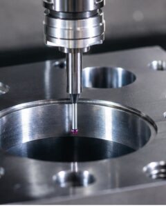
A datum feature that is small, inaccessible or unstable may be challenging to establish consistently. The resulting measurement setup can become more complicated than necessary. A well-chosen datum, on the other hand, often corresponds to a robust functional surface or feature that can be referenced reliably.
This does not mean datums should be selected solely for inspection convenience. Their primary purpose is to communicate design intent. However, manufacturability and measurability should both be considered when creating a practical engineering drawing.
If a component is difficult to locate consistently using the specified datum structure, it may be worth reviewing whether the references genuinely represent the intended assembly conditions.
Common Datum Selection Problems
One common issue is choosing datums simply because they are convenient drawing surfaces rather than because they represent how the component functions.
Another is using too many unrelated datum schemes across the same component, which can make the drawing harder to interpret and potentially create conflicting requirements.
Small or irregular surfaces can also create problems when used as major datum features. If a feature cannot provide a stable reference, inspection may become unnecessarily sensitive to local variation.
Designers should also avoid assuming that a datum automatically imposes a tight tolerance on the datum feature itself. If the feature needs specific flatness, size or form control, those requirements may need to be specified separately.
The datum establishes a reference framework; it does not replace all other dimensional and geometric controls.
Datums and Tolerance Stack-Up
A good datum strategy can help reduce problems caused by tolerance accumulation.
If a series of features is dimensioned progressively from one another, small variations can accumulate across the component. Referencing important features from a common functional datum can often make the design intent clearer.
For example, several hole locations may all be functionally related to the same mounting face and locating bore. Controlling them from those common references can be more useful than creating a chain of dimensions from one hole to the next.
This does not eliminate manufacturing variation, but it helps ensure that allowable variation is being controlled relative to the features that matter most. For precision assemblies, this can make both production and inspection more straightforward.
Datums on Thin or Flexible Components
Datum selection becomes particularly important where components are thin or flexible.
A large thin surface might appear to be an obvious primary datum, but if the part can easily distort under its own weight or clamping pressure, establishing that reference consistently may require careful support.
Inspection conditions can influence the measured result as well. A flexible component resting on three points may behave differently from one forced against a large flat fixture. Designers and machining suppliers therefore need to consider the physical behaviour of the component as well as the theoretical datum framework.
This is particularly relevant for thin-wall CNC machining, where workholding, residual stress and inspection strategy can all influence the final geometry.
Designing a Practical Datum Structure
A useful datum system should communicate how the component is intended to locate and function without making manufacture or inspection unnecessarily complicated.
The primary datum is often a major functional mounting or locating feature. Secondary and tertiary datums can then establish the remaining orientation and position.
When reviewing a datum structure, useful questions include whether the datum features correspond to real assembly interfaces, whether they are accessible for inspection, whether they provide stable references and whether related geometric tolerances genuinely need to use the same framework.
Consistency is valuable. If several critical features work together in the same assembly, referencing them to a common functional datum structure can help communicate their relationship much more clearly than treating each feature independently.
When Should Datum Requirements Be Discussed With the CNC Supplier?
Most well-defined engineering drawings can be manufactured directly without extensive discussion. However, early review can be useful where a component contains complex datum structures, very tight positional tolerances, multiple precision bores, thin flexible features or several machining setups.
A supplier may identify that a particular reference is difficult to establish consistently or that the machining sequence could benefit from a small design adjustment. This is particularly valuable before repeat production begins, when modifications to the drawing or manufacturing route are easier to implement.
The objective is not to change the functional intent, but to ensure that the specified datum framework can be reproduced reliably throughout machining and inspection.
Datums and Precision CNC Machining at Tarvin Precision
Datums provide the reference framework that connects component design, CNC machining and inspection. By defining how important features relate to one another, they help ensure that dimensions and geometric tolerances are assessed from consistent functional references.
At Tarvin Precision, we manufacture CNC-machined components for demanding engineering applications where datum structures, geometric tolerances and controlled inspection may all form part of the drawing requirements.
Where components include complex positional relationships, precision bores, tightly controlled surfaces or other demanding geometric features, reviewing the datum structure before manufacture can help establish an appropriate machining and inspection strategy.
If you have an engineering drawing or CAD model you would like us to review, contact Tarvin Precision to discuss your CNC machining requirements.
Frequently Asked Questions
Datums can initially appear complicated because engineering drawings may combine datum letters, feature-control frames and several geometric tolerances. In practice, their purpose is straightforward: they create repeatable references that allow important component features to be manufactured, assembled and inspected in a consistent way.
What does a datum mean on an engineering drawing?
A datum is a theoretically exact reference such as a plane, axis or point used to establish the position or orientation of other features on a component.
What is the difference between a datum and a datum feature?
The datum feature is the physical manufactured surface, hole or feature on the component. The datum is the ideal reference derived from that feature.
What do datum A, B and C mean?
A, B and C identify datum features and commonly represent the primary, secondary and tertiary references used to establish the component’s datum framework.
Does datum A always have to be a flat surface?
No. Although a large flat mounting surface is often used as a primary datum, cylindrical features and other suitable geometry can also establish datums depending on component function.
Why are datums important for CMM inspection?
Datums allow the CMM to establish a repeatable coordinate system before measuring related surfaces, holes and geometric tolerances.
Can a bore be used as a datum?
Yes. A precision bore can establish a datum axis where that feature provides an important functional location in the finished assembly.
Do datums affect CNC machining?
They can. Although drawing datums do not always dictate the exact manufacturing setup, they often influence machining sequence, workholding strategy and how related features are produced and inspected.
Should datum selection be based on how the component assembles?
Generally, functional assembly relationships are an important consideration. A good datum structure often reflects the surfaces and features that locate the component in its final application.