
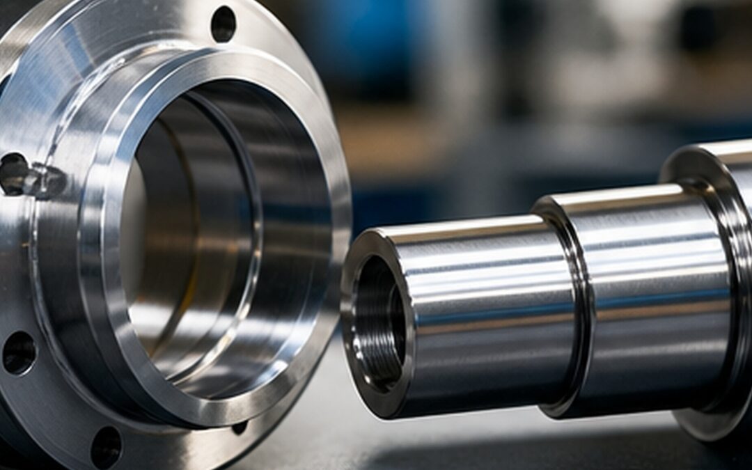
When two precision-machined components are designed to fit together, their nominal dimensions only tell part of the story. What really determines how the parts assemble is the relationship between the tolerances applied to the mating features.
A shaft nominally specified as 20 mm and a bore also nominally specified as 20 mm could behave in very different ways depending on their permitted dimensional limits. The shaft might slide freely into the bore, it might locate with almost no perceptible movement, or it might need to be pressed into position with significant force.
These different relationships are described using clearance, transition and interference fits. Understanding the difference between a clearance fit vs interference fit is useful for designers, engineers and buyers because it helps connect component dimensions with real assembly behaviour. It also helps machining suppliers understand the functional requirement behind a drawing rather than simply producing isolated dimensions.
For CNC-machined components, fit requirements can influence the machining method, the tolerances applied to holes and shafts, surface finish, inspection strategy and ultimately manufacturing cost. A general clearance hole may be straightforward to drill, while a closely controlled bearing bore, press-fit shaft or threaded holes may require additional finishing and measurement. The correct fit should therefore be selected according to how the finished assembly needs to function.
What Is an Engineering Fit?
An engineering fit describes the dimensional relationship between two mating features, most commonly a shaft and a hole or bore. Both features have a nominal size and an allowable tolerance range. The way those two tolerance zones overlap, or remain separated, determines the resulting fit.
If the hole is always larger than the shaft, the assembly has clearance. If the shaft is always larger than the hole, there is interference. If the two tolerance zones overlap, the final result may contain either slight clearance or slight interference depending on the actual dimensions of the individual components. This is why nominal size alone is not enough to describe how two parts will behave.
Two features may both be described as 25 mm nominal diameter while their tolerance limits create completely different assembly conditions. The designer must therefore consider both the nominal dimension and the permitted variation around it. In practical terms, an engineering fit answers the question: how should these two components interact when manufactured within tolerance?
What Is a Clearance Fit?
A clearance fit ensures that the hole is always larger than the mating shaft. Even when the hole is at its smallest acceptable size and the shaft is at its largest acceptable size, some clearance remains between the two. This makes clearance fits useful where components need to move, rotate, slide, assemble easily or be removed repeatedly. Common examples include:
- bolts passing through clearance holes;
- shafts rotating inside bushes;
- sliding pins;
- removable shafts;
- guide components;
- parts that require straightforward assembly.
The amount of clearance can vary significantly depending on function. A bolt hole may have relatively generous clearance because accurate location is provided elsewhere. A rotating shaft inside a precision bush may require only a small amount of controlled clearance to allow movement while limiting unwanted play.
Too much clearance can introduce vibration, noise, misalignment or poor positional control. Too little clearance can increase friction, create assembly difficulty or cause the parts to bind as operating temperature changes. A clearance fit is therefore not simply “a loose fit”. It can range from deliberately free-running to very closely controlled.
What Is an Interference Fit?
An interference fit is the opposite condition. The shaft or male feature is larger than the mating hole throughout the permitted tolerance range. This creates dimensional overlap between the components. The parts will not assemble freely and normally require a controlled method of installation. Depending on the size and application, this might involve:
- pressing one component into another;
- heating the outer component;
- cooling the inner component;
- using a combination of thermal and mechanical assembly methods.
Interference fits are often used where relative movement between the precision machined components must be prevented. Typical applications include bearings, bushes, dowel pins, gears, hubs, pulleys and other permanently or semi-permanently located components.
The amount of interference is critical. Too little may fail to retain the component securely, while excessive interference can generate high assembly forces, distort the parts or even damage the surrounding material. For this reason, an interference fit should be selected according to the materials, diameter, wall thickness, load, operating temperature and assembly method. More interference does not automatically create a better assembly.
What Is a Transition Fit?
A transition fit lies between clearance and interference. The tolerance zones of the mating features overlap, so the finished assembly may have a small amount of clearance or a small amount of interference depending on where each component falls within its tolerance range.
Transition fits are commonly used where accurate location is required but heavy press fitting would be unnecessary. Applications can include:
- precision locating components;
- hubs;
- removable assemblies;
- some dowel applications;
- components requiring close alignment.
A transition fit can provide a very close relationship between the features while still allowing a degree of assembly flexibility. However, the designer should understand that the final condition is not guaranteed to be either clearance or interference. One pair of components may slide together with slight resistance, while another pair manufactured within exactly the same drawing limits may require light pressing. This variability is acceptable only where the assembly can tolerate both outcomes.
Standard systems of fits, such as the ISO 286 system of limits and fits, are useful because they provide recognised tolerance combinations for different types of assembly.
Clearance Fit vs Interference Fit: The Main Difference
The key difference between the two is whether clearance or dimensional overlap is guaranteed.
With a clearance fit, the smallest permitted hole is still larger than the largest permitted shaft. The parts therefore always have some amount of space between them.
With an interference fit, the largest permitted hole is still smaller than the smallest permitted shaft. The components therefore always overlap dimensionally and need some form of force or thermal assistance to assemble.
A transition fit allows the tolerance zones to overlap. This distinction becomes particularly important for precision assemblies because the difference between a shaft that slides into a bore and one that must be pressed into it can be only a small number of microns. That small dimensional change can have a large effect on assembly behaviour.
Hole and Shaft Tolerance Zones
Engineering fit systems describe tolerance zones relative to a nominal dimension. These tolerance zones define both the amount of allowable variation and where that variation sits in relation to the nominal size. For example, a shaft tolerance may lie slightly below nominal while the hole tolerance lies slightly above nominal. This creates guaranteed clearance.
For an interference fit, the shaft tolerance zone may sit above the hole tolerance zone so that dimensional overlap is always present. Standard systems of fits are useful because they provide recognised combinations for different types of assembly. This can be more effective than creating arbitrary CNC machining tolerances for every new component.
Using established fit systems helps designers communicate intent clearly and gives machining suppliers a familiar basis for manufacture and inspection.
The Hole Basis System
The hole basis system is widely used in mechanical engineering. In this approach, the hole acts as the main reference and different shaft tolerance zones are selected to produce the required clearance, transition or interference fit.
This is often practical because holes are commonly produced using standard tooling such as drills, reamers and boring operations. Maintaining a consistent hole basis can simplify tool selection while allowing the shaft dimension to be adjusted according to the required fit.
For example, the same nominal bore might be used with one shaft tolerance for a free-running clearance fit and another shaft tolerance for a transition or interference condition. This does not mean the hole basis system is always the correct choice, but it is common because it aligns well with many practical manufacturing methods.
The Shaft Basis System
The shaft basis system works in the opposite way. Here, the shaft tolerance remains the main reference while different hole tolerance zones are selected to achieve the required fit.
This approach can be useful where shaft dimensions are fixed by another component, standard stock size or purchased part. For example, a commercially available shaft may already have a defined tolerance. The mating hole can then be selected or machined to create the required clearance or interference.
Both hole basis and shaft basis systems are valid. The choice depends on the design and manufacturing situation. The important point is that the chosen relationship is clearly communicated on the engineering drawing.
Fits and CNC-Machined Holes
The required fit can strongly influence how a hole or bore is manufactured.
A general bolt clearance hole may be produced directly by drilling because the diameter tolerance is relatively generous. A precision locating hole may require additional operations such as reaming or boring. A bearing bore may require close control of not only diameter but also roundness, cylindricity, position and surface finish.
This demonstrates why fit requirements should not be considered purely as numbers on a drawing. The chosen tolerance influences the manufacturing route. As tolerances become tighter, more controlled machining processes may be required. The machinist may also need to leave material for a dedicated finishing operation rather than producing the final diameter in one stage. Inspection becomes more important as well, particularly where the tolerance range is small.
Fits and CNC-Machined Shafts
Shafts used for close fits are commonly produced using CNC turning. The final diameter can be influenced by cutting tool condition, machine stability, material behaviour and temperature. A precision shaft may therefore be rough machined first before a controlled finishing pass brings it to the required final size.
Where several critical diameters exist on the same shaft, relationships such as concentricity, runout and shoulder position may also matter. A shaft that is the correct diameter but geometrically inconsistent may still create problems in an assembly.
The finished surface condition can matter too. A rough shaft can increase friction or assembly force even when the measured diameter falls within tolerance.
Clearance Fits for Moving Components
Moving assemblies often depend on carefully controlled clearance. A rotating shaft, for example, needs enough space to turn freely without binding. However, excessive clearance may create vibration, reduced positional accuracy or premature wear.
Lubrication can also influence the required relationship. Certain moving interfaces rely on a lubricant film between the surfaces, which requires sufficient space to form and remain stable during operation. Temperature can affect this clearance as well. If the shaft and housing expand at different rates, the available space may change during use.
This is why clearance fits should be selected in the context of the complete application rather than simply choosing a standard loose fit.
Interference Fits for Bearings
Bearings are a familiar application of controlled interference fits. A bearing outer race may need to remain securely located in a housing, while an inner race may need to be retained on a shaft. 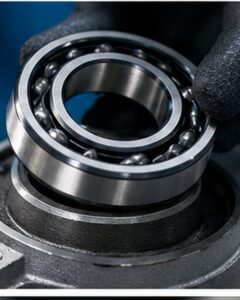
The correct fit depends on factors such as load direction, operating conditions, material and bearing manufacturer’s recommendations. Too little interference can allow unwanted movement between the bearing and its seat. Too much can make assembly difficult or distort the bearing geometry.
This becomes especially important in thin or lightweight housings, where heavy interference can expand or distort the surrounding material. The bore may have been machined accurately before assembly but then change shape after the bearing is pressed in. This is another reason fit selection must consider the entire component rather than simply the nominal diameter.
Interference Fits for Bushes
Bushes are another common press-fit application. A bush may be pressed into a machined housing to provide a durable bearing or locating surface. The interference needs to retain the bush securely without damaging the housing.
The designer should consider the wall thickness around the bore, particularly in aluminium or other relatively soft materials. If the surrounding section is thin, excessive interference can cause distortion or cracking. It may also affect the internal diameter of the bush after installation.
For precision assemblies, the designer may therefore need to consider both the installed condition and the pre-assembly dimensions.
Fits for Dowel Pins
Dowel pins are commonly used to locate components accurately.
A typical arrangement may use an interference or transition fit in one component so the dowel remains fixed, while the mating component uses a closer clearance fit. This allows the assembly to locate accurately without requiring the dowel to be removed every time the parts are separated.
Dowel applications also highlight the relationship between fit and position. A dowel hole can have the correct diameter but still cause assembly problems if it is not located accurately. Where two or more dowels are used together, positional tolerances can become particularly important because even small errors can prevent the mating component from fitting. This is why dowel holes may combine close size control with true position tolerance.
Fits and Precision Bores
Precision bores may carry shafts, bearings, bushes, seals or other functional components.
The selected fit determines the allowable diameter range, but diameter is only part of the requirement. Roundness, cylindricity, alignment and surface finish may also affect performance.
A bore that measures within size tolerance at one location but is tapered or out of round can still create assembly problems. Likewise, a bore may have excellent geometry but be positioned incorrectly relative to another feature. For this reason, fit specifications should be considered alongside broader geometric tolerances.
Fits and Surface Finish
Surface roughness becomes more important as fits become closer.
Microscopic peaks on a machined surface can influence how two components contact one another. On an interference fit, roughness can affect assembly force and the way load is transferred between surfaces.
For a sliding or rotating clearance fit, excessive roughness may contribute to friction or wear. This is why surface finish Ra may be specified on critical shafts or bores in addition to the dimensional tolerance. A precision fit does not automatically require a polished surface, but the finish should be appropriate to the function.
Fits and Temperature
Temperature can have a significant effect on close-fitting components because materials expand and contract. A steel shaft and aluminium housing, for example, will not necessarily change size at the same rate as temperature changes. An assembly with suitable room-temperature clearance could become tighter or looser in operation.
Temperature is also sometimes used deliberately during assembly. Heating the outer component increases the bore diameter temporarily, while cooling the shaft or insert reduces its size. This can allow an interference fit to be assembled with less mechanical force. Once the parts return to normal temperature, the intended interference is restored. For equipment operating across a wide temperature range, thermal behaviour should therefore be considered during design.
Material Selection and Fit Behaviour
Different materials respond differently to interference and loading.
Steel, aluminium, stainless steel, bronze and engineering plastics all have different stiffness, strength and thermal expansion characteristics. A press fit that is appropriate for a steel housing may be excessive for a thin aluminium component.
Material hardness can also affect assembly behaviour. When one part is substantially harder than the other, the softer material may deform more during installation. This may be entirely acceptable if the fit is designed accordingly, but it should be considered rather than left to chance.
Wall Thickness Around Interference Fits
The material surrounding a press-fit bore needs enough stiffness and strength to support the interference.
A thick housing can resist the assembly forces more effectively than thin-walled components. If the wall thickness is limited, pressing in a bearing or bush can expand the housing locally or distort nearby features.
This can be particularly important where another precision bore or mounting surface sits close to the press-fit location. The fit therefore needs to be considered alongside thin-wall machining, material properties and overall component geometry. The strongest possible interference is rarely the best engineering solution.
Tolerance Stack-Up and Fits
The fit between a shaft and bore does not exist in isolation.
Other component dimensions and geometric tolerances affect whether the complete assembly works. A shaft may fit perfectly inside its bore while the bore itself is positioned slightly incorrectly relative to another part. Likewise, a series of mating components can accumulate dimensional variation across an assembly. This is known as tolerance stack-up.
Good datum selection and geometric tolerancing can help control the relationships between important features without unnecessarily tightening every individual dimension. This can create a more robust design and a more practical manufacturing process.
Measuring Precision Fits
The fit is usually verified by measuring the individual mating features.
Hole and bore diameters may be checked using bore gauges, plug gauges, internal micrometers or coordinate measuring machines. Shaft diameters are commonly inspected with micrometers or dedicated gauges.
For very close tolerances, the measurement method must be capable of resolving the required variation reliably. Temperature control may also become important because small thermal changes can affect dimensions. The inspection environment, component temperature and measurement equipment should therefore be appropriate to the specified tolerance.
Why Tight Fits Increase Machining Cost
Close fits can require greater manufacturing control.
A shaft or bore may need additional finishing passes to achieve the required size consistently. Tool wear may need to be monitored more closely, and in-process inspection may become more frequent.
The machining supplier may also need specialist measuring equipment to verify the finished feature. Where the tolerance band is particularly narrow, small changes in temperature or material condition may become relevant. This does not mean close fits should be avoided. Where the assembly genuinely requires them, the additional control is justified. The issue arises when tight fits are specified where a more generous tolerance would perform equally well.
Common Fit Specification Mistakes
One common mistake is making the fit tighter than necessary. A component that simply needs to assemble reliably may not benefit from a close transition fit.
Another is concentrating only on diameter and overlooking surface finish, position or roundness. A bore can be technically within diameter tolerance and still fail function if its axis is misplaced or the surface condition is unsuitable.
Designers may also overlook how an interference-fit component will actually be assembled. If a bearing requires substantial pressing force, there needs to be a practical way to support the housing and apply that load. Temperature and material differences can also be forgotten, particularly in components used outside controlled indoor conditions.
Choosing the Correct Fit
The best fit begins with the intended function.
If the two parts need to move freely, rotate or assemble easily, a clearance fit is normally appropriate. If accurate location is needed with very little movement, a transition fit may be suitable. If the parts must remain securely joined without relative motion, an interference fit may be required. The designer should also consider:
- assembly method;
- operating temperature;
- material combination;
- lubrication;
- service loads;
- wall thickness;
- whether future disassembly is required;
- inspection capability.
Using recognised fit systems can provide a good starting point, but the final choice should always reflect how the component needs to perform in service.
When Should You Discuss Fits With Your CNC Supplier?
Most standard fit requirements can be manufactured directly from a clear engineering drawing.
Discussion becomes particularly valuable where a component contains very close transition fits, significant interference, thin surrounding walls, precision bearing locations or several mating features whose tolerances interact.
A machining supplier may be able to identify a feature that would benefit from a small tolerance adjustment or a different manufacturing approach. Resolving these issues before production is particularly valuable for repeat components, because a small improvement to the process can be carried across future batches.
Precision Fits at Tarvin Precision
Clearance, transition and interference fits provide a structured way of controlling how CNC-machined components assemble and interact.
The correct fit depends on more than nominal size. Hole and shaft tolerances, material, surface finish, feature position, geometry and operating temperature can all influence the finished assembly.
At Tarvin Precision, we manufacture CNC-machined components for demanding engineering applications where precision bores, shafts, dowel features, bearing locations and controlled fits may form part of the drawing requirements. Where components contain close-tolerance mating features, reviewing the design before manufacture can help establish an appropriate machining and inspection strategy.
If you have an engineering drawing or CAD model you would like us to review, contact Tarvin Precision to discuss your CNC machining requirements.
Frequently Asked Questions
Clearance, transition and interference fits are based on the relationship between the permitted sizes of mating components rather than their nominal dimensions alone. The questions below cover some of the most common issues designers and buyers may encounter when specifying precision shafts, holes and bores.
What is the difference between a clearance fit and an interference fit?
A clearance fit guarantees a gap between the mating components, while an interference fit guarantees dimensional overlap and normally requires force or thermal assistance for assembly.
What is a transition fit?
A transition fit has overlapping tolerance zones. Depending on the actual manufactured dimensions, the assembly may contain either slight clearance or slight interference.
What is a hole basis fit?
In a hole basis system, the hole acts as the main reference and different shaft tolerance zones are selected to create the required type of fit.
What is a shaft basis fit?
In a shaft basis system, the shaft acts as the main reference and the hole tolerance is changed to produce the required clearance, transition or interference condition.
Can surface finish affect a precision fit?
Yes. Surface roughness can influence friction, contact behaviour and assembly force, particularly with transition and interference fits.
Can an interference fit damage a component?
Potentially. Excessive interference can distort thin housings, damage components or generate excessive assembly forces, which is why the fit should reflect the material and geometry involved.
Why are bearing bores tightly controlled?
Bearing bores may need accurate diameter, roundness, surface finish and position to ensure the bearing is retained correctly and operates as intended.
Why are dowel holes often specified with tight tolerances?
Dowel pins are generally used to locate components accurately, so both hole size and position can be important to reliable assembly.
Can temperature change the fit between two components?
Yes. Materials expand and contract as temperature changes, which can alter the amount of clearance or interference between mating parts.
Are interference fits always pressed together?
No. Heating the outer component or cooling the inner component can also be used to make assembly easier.
Do tighter fits increase CNC machining cost?
They can. Close tolerance fits may require additional finishing passes, more frequent measurement, tighter process control and additional inspection.