
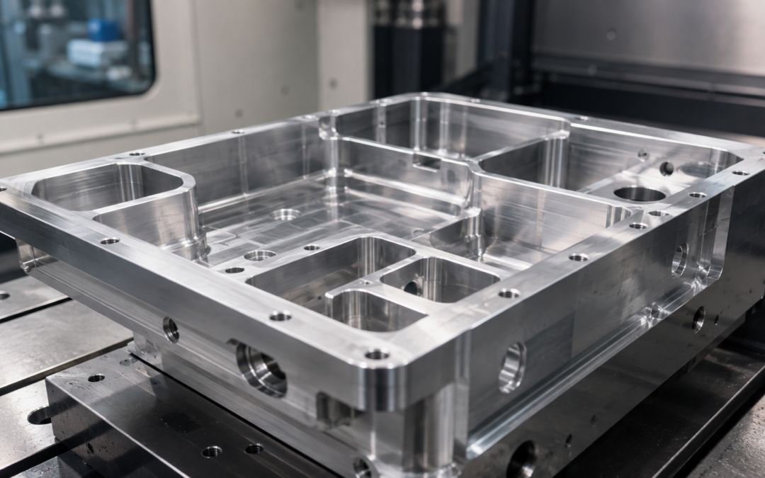
Internal corner radii can appear to be a relatively minor detail on a CNC-machined component. In practice, they can influence tool selection, machining strategy, cycle time, surface finish and manufacturing cost. The reason is simple: a rotating milling cutter is round.
Unlike some manufacturing processes, conventional CNC milling cannot normally produce a perfectly sharp 90-degree internal corner. The cutting tool leaves a radius that corresponds, at least in part, to its own geometry. For designers and buyers of precision-machined components, understanding the relationship between CNC machining internal corner radius, cutter diameter and feature depth can help avoid unnecessarily difficult designs.
A slightly larger internal radius may allow the use of a larger, more rigid cutting tool. That can improve machining stability and, depending on the component, reduce machining time. Conversely, specifying a very small radius in a deep pocket may require a much smaller tool with greater reach. The feature might still be manufacturable, but the machining process can become slower and more demanding. This guide explains why.
What Is an Internal Corner Radius?
An internal corner radius is the curved transition formed where two internal surfaces meet. A common example is the corner at the bottom or side of a CNC-milled pocket.
If a designer creates a rectangular pocket in CAD, the model may initially appear to have perfectly sharp internal corners. In CNC milling, however, those corners will generally need some form of radius. The size of the radius depends on factors including:
- cutter diameter;
- pocket depth;
- tool accessibility;
- component geometry;
- required fit;
- machining strategy.
Internal radii should therefore be considered during the design stage rather than treated simply as a manufacturing detail. This is especially important when a pocket is deep, narrow or surrounded by relatively thin material.
Why Can’t CNC Milling Produce a Perfectly Square Internal Corner?
A CNC milling cutter rotates around a central axis. Because the tool itself has a circular cross-section, it cannot remove material right into a perfectly sharp internal corner in the same way that a square cutting edge could.
If a 10 mm diameter end mill is used to machine a pocket, for example, the cutter has a 5 mm radius. The final internal corner geometry will therefore reflect the toolpath and the size of the cutter being used. This does not usually cause a problem because most CNC-machined components can be designed with a reasonable corner radius. Problems occur when a drawing calls for a near-sharp internal corner without a genuine functional need.
In that situation, the machining supplier may need to use a much smaller cutting tool, add additional operations or discuss an alternative design. The important principle is that an internal corner radius is a normal consequence of CNC milling, not an indication of poor machining accuracy.
How Cutter Diameter Affects Internal Corner Radius
The diameter of the cutter plays a major role in the radius that can be produced. A larger cutter naturally produces a larger radius. A smaller cutter can access a tighter corner. 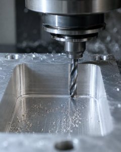
At first glance, this might suggest that the solution to a small-radius requirement is simply to use a smaller end mill. In reality, the diameter of the cutter affects much more than geometry. Larger cutters are generally more rigid and can often remove material more efficiently. Smaller tools may need to operate with lighter cutting conditions, particularly where the required feature is deep. This means reducing an internal radius can sometimes affect:
- cutting speed;
- feed rate;
- depth of cut;
- number of machining passes;
- tool life;
- risk of tool deflection;
- cycle time.
The radius specified on the drawing can therefore have a direct effect on the manufacturing strategy.
Why Tool Rigidity Matters
A cutting tool needs enough rigidity to resist the forces generated during machining. As cutter diameter decreases, tool rigidity generally reduces.
The effect becomes more significant when the cutter also needs to project a considerable distance from the tool holder. A short, relatively large-diameter cutter is normally far more rigid than a long, slender one. This matters because tool deflection can influence:
- dimensional accuracy;
- surface finish;
- wall straightness;
- vibration;
- tool life;
- machining consistency.
A very small internal corner radius at the bottom of a deep pocket can therefore create a difficult combination. The machine may require a small-diameter tool to achieve the radius, but the pocket depth may require the same tool to have considerable reach. This combination of small diameter and long overhang is often what turns a seemingly simple radius requirement into a more challenging machining operation.
Pocket Depth and Corner Radius Should Be Considered Together
One of the most important design considerations is the relationship between internal radius and pocket depth.
A 2 mm internal radius in a shallow feature may present relatively little difficulty. The same 2 mm radius at the bottom of a deep pocket can be much more demanding. The cutter must physically reach the required depth while remaining sufficiently rigid to machine the feature accurately. This is why it can be misleading to specify corner radius without considering the rest of the geometry. For CNC-machined pockets, designers should consider:
- how deep the pocket is;
- how narrow the opening is;
- whether the tool has clear access;
- whether adjacent walls restrict tool diameter;
- whether a larger radius would affect component function.
A modest increase in radius can sometimes make a substantial difference to the available tooling options.
Why Small Internal Radii Can Increase Machining Time
Machining time is influenced by many factors, but tool diameter is an important one. A large cutter can remove a greater volume of material during roughing. A smaller cutter will generally remove less material per pass. If the entire feature has to be machined using a small cutter simply because of one tight corner radius, cycle time can increase considerably.
A common machining strategy is therefore to use a larger tool for the majority of material removal and then introduce a smaller tool only where needed. This can be efficient, but it adds another operation and potentially another tool change. The smaller cutter may also require:
- lower cutting forces;
- more machining passes;
- reduced step-down;
- slower feed conditions;
- additional finishing passes.
None of these factors necessarily makes the component difficult to manufacture, but together they can affect the quotation and lead time. For this reason, an unnecessarily small internal radius can add cost despite representing only a tiny area of the finished component.
Larger Corner Radii Can Improve Machining Efficiency
Where component function permits, larger internal radii can make CNC machining more straightforward. A larger radius may allow the machinist to use a larger-diameter cutter. Potential benefits include:
- increased tool rigidity;
- improved cutting stability;
- greater material-removal rates;
- reduced machining time;
- improved tool life;
- better surface consistency;
- reduced risk of chatter or deflection.
The exact benefit will depend on the part. Increasing a radius from 2 mm to 3 mm, for example, will not automatically transform the manufacturing cost of every component. However, if the change allows a significantly more rigid tool or removes the need for a secondary small-tool operation, the effect can be meaningful. The role of design for manufacture is about identifying these relatively small changes before the drawing is finalised.
Corner Radius and Tool Engagement
Internal corners can also create changes in cutter engagement. As a milling cutter moves through a straight section of a pocket, the amount of tool engaged with the material may be relatively consistent. Entering a tight internal corner can increase engagement. This creates additional cutting load and can increase the risk of vibration or tool deflection.
Modern machining and CNC tooling strategies can help manage these changes through controlled toolpaths and appropriate feeds. Even so, the geometry of the component still matters. A more generous internal radius can make the cutter’s path through the corner smoother and reduce sudden changes in tool engagement. This can be particularly useful when machining harder materials or deeper features. The effect is another example of how geometry that appears simple on a CAD model can influence the actual cutting process.
Does Every Internal Corner Need the Same Radius?
No. Different areas of a component may have completely different functional requirements. Some corners may simply define the boundary of a clearance pocket and could accept a relatively generous radius. Others may need to accommodate a mating component. This is why automatically applying the smallest possible radius to every corner is rarely the best design approach. A useful question during design is:
What is this internal corner required to do?
If nothing needs to fit precisely into that corner, a larger radius may be possible. If another part does need to fit, there may still be alternative options. For example, the mating component itself may have an external chamfer or radius that provides adequate clearance. Looking at both mating parts together can sometimes reveal that a difficult internal corner requirement is unnecessary.
What If a Mating Part Has a Square External Corner?
A common design situation involves placing a nominally rectangular component inside a milled pocket. The inserted component has external corners, while the CNC-machined pocket contains internal radii. If adequate clearance is not provided, the corners can interfere even when the overall length and width dimensions are correct.
There are several ways this can sometimes be addressed. One option is to add a suitable radius or chamfer to the external corner of the mating component. Another is to increase the radius and dimensions of the pocket. Where a genuinely square fit is required, additional manufacturing methods or specialised features may need to be considered.
The best solution depends on component function, but it is generally preferable to address the issue deliberately in the design rather than discovering an interference problem during assembly.
Alternatives When a Sharp Internal Corner Is Required
There are applications where a relatively sharp internal corner is genuinely necessary. CNC milling is not the only manufacturing process available, and alternative approaches may be considered depending on the design. Options can include specialised machining strategies, additional processes or modifying the geometry to provide local clearance.
One common design technique is to provide corner relief. Rather than demanding that the entire internal corner is perfectly square, the designer intentionally removes a small amount of additional material around the corner. This allows a square external component to fit into a milled pocket despite the round cutter geometry. These relief features are sometimes referred to as dog-bone or corner relief features, depending on their shape.
They are not suitable for every component, but they demonstrate an important point: sometimes the best solution is not to fight the characteristics of the manufacturing process but to design around them.
Internal Corner Radii and Surface Finish
Small-radius features can also affect surface finish. A slender tool is more susceptible to deflection and vibration than a larger, more rigid cutter. If the cutter begins to vibrate, marks may appear on the machined surface.
Machining parameters, toolpath and tool condition all contribute to surface quality, but component geometry sets the conditions within which those decisions must be made. Deep pockets with tight corners are particularly demanding because access and tool rigidity are both constrained.
Where surface finish is important, allowing a practical internal radius can give the machinist more options for achieving a stable finishing operation. This can be especially relevant where the pocket surface forms part of a functional interface or where cosmetic appearance matters.
Specifying Internal Radii on Engineering Drawings
A clear engineering drawing should communicate the required geometry without creating unnecessary ambiguity. Where internal corner radii are functionally important, they should be specified appropriately.
Designers should avoid assuming that a machinist can simply produce a sharp internal corner because the CAD model displays one. Equally, there is little benefit in applying a very tight radius tolerance where the exact radius has no functional significance.
It may be more useful to specify a maximum radius or a range that gives the machining supplier some flexibility in tool selection. The appropriate approach will depend on the component and drawing standard being used. The broader principle is to communicate functional requirements, not impose unnecessary manufacturing restrictions.
How Internal Corner Radius Can Affect CNC Machining Cost
The cost of a CNC-machined component is driven by the complete manufacturing route. Internal radius is only one factor, but it can influence cost when it changes the required tooling or machining time. A particularly restrictive radius might require:
- an additional cutting tool;
- longer cycle time;
- slower finishing passes;
- additional tool changes;
- more complex programming;
- specialist tooling;
- additional inspection.
For a one-off prototype, the effect might be relatively limited. For repeated batches, additional cycle time on every component can become more significant. This is why a small design change made before manufacture can sometimes provide savings across the life of a component. It is also why the lowest possible radius should not automatically be considered the best engineering choice.
Internal Corner Radius and Thin-Walled Components
Corner radius can become particularly important when a pocket is surrounded by thin walls. A small radius may require a small tool. A deep pocket may require that tool to have considerable reach. Meanwhile, the thin wall itself can be susceptible to cutting forces. The result for thin-walled components is a combination of tool flexibility and part flexibility.
Where possible, using a larger internal radius can help by allowing a more rigid tool and potentially reducing the cutting forces required during finishing. This connection is useful when considering complex CNC machining components because individual design features rarely exist in isolation. Wall thickness, feature depth, cutter access, corner radius and tolerance all interact.
Design for Manufacture: Questions to Ask Before Finalising a Radius
Before finalising the internal radii on a CNC-machined component, it can be useful to ask several questions.
Does the corner need to be this tight?
If there is no functional reason for the smallest radius, increasing it may simplify machining.
How deep is the feature?
A small radius becomes more challenging when combined with significant depth.
Does another component need to fit into the corner?
If so, could the mating component use a chamfer or external radius instead?
Can the same radius be used throughout the component?
Standardising radii may reduce the number of tools required.
Could a larger cutter be used if the radius changed slightly?
This may improve machining efficiency and rigidity.
Is the radius tolerance tighter than the function requires?
Avoiding unnecessarily restrictive tolerances can give the manufacturer more flexibility.
These questions do not require the designer to become a machining specialist. They simply help ensure that manufacturing considerations are included while design changes are still relatively easy to make.
When Should You Ask Your CNC Machining Supplier for DFM Advice?
Early discussion can be particularly valuable for components containing:
- deep pockets;
- very small internal radii;
- thin walls;
- narrow slots;
- difficult tool access;
- tight tolerances;
- multiple mating features.
A machining supplier may be able to identify a radius or feature that could be adjusted without affecting component function. This is particularly useful before producing a batch of components. Once drawings, assemblies and other documentation are fully released, even a simple radius change can become more administratively difficult.
A short design-for-manufacture review at an earlier stage can therefore help reduce risk and confirm that the proposed geometry is practical to machine.
CNC Machining Complex Internal Features at Tarvin Precision
Internal corner radii are a good example of the relationship between component design and the practical realities of CNC machining.
A small radius may look like a minor drawing requirement, but its interaction with cutter diameter, feature depth, tool rigidity and machining strategy can influence both manufacturing time and cost.
At Tarvin Precision, we manufacture precision CNC-machined components for a range of engineering applications, including parts with pockets, internal features, tight CNC machining tolerances and demanding geometries. Where appropriate, reviewing component geometry before manufacture can help identify opportunities to improve machinability while maintaining the required function.
If you have a drawing or CAD model containing deep pockets, small internal radii or other challenging features, contact Tarvin Precision to discuss your machining requirements.
Frequently Asked Questions
Some of the FAQs we hear most about CNC machining internal corner radii are as follows.
What is the minimum internal corner radius for CNC milling?
There is no single minimum radius that applies to all CNC-milled components. The practical minimum depends on feature depth, cutter access, tool diameter, material, tolerance and the required surface finish. Smaller radii generally require smaller and potentially less rigid tooling.
Why do CNC-machined pockets have rounded corners?
Milling cutters are round. When a rotating cutter machines an internal corner, its geometry naturally creates a radius rather than a perfectly sharp 90-degree corner.
Does a smaller internal radius make CNC machining more expensive?
It can. A smaller radius may require a smaller cutter, additional machining operations, reduced cutting parameters or longer cycle times. The effect depends on the component geometry and production quantity.
Is a larger internal corner radius better for CNC machining?
Where component function allows it, a larger radius often provides more machining flexibility. It may allow the use of a larger and more rigid cutter, potentially improving stability, tool life and machining efficiency.
Can CNC machining produce a perfectly square internal corner?
Standard CNC milling cannot normally produce a completely sharp internal corner because the cutting tool is round. Alternative manufacturing methods or design features such as corner relief may be used where a square-fitting component is required.
How does pocket depth affect internal corner radius?
The deeper the pocket, the greater the tool reach generally required. Combining a deep pocket with a very small radius can require a long, slender cutting tool, which may be more susceptible to deflection and vibration.
What radius should I specify on a CNC-machined part?
The radius should be based on component function while providing as much manufacturing flexibility as practical. If the exact radius is not functionally critical, discussing the feature with the machining supplier can help avoid unnecessarily restrictive geometry.