

Aerospace design for manufacture is the process of developing components that meet their functional, safety and performance requirements while also being practical to machine, inspect, finish and reproduce. It brings manufacturing knowledge into the design stage so that potential production problems can be identified before drawings are released, tooling is ordered or components enter full-scale production.
In aerospace engineering, small design decisions can have a significant effect on machining time, inspection complexity, lead time and component cost. A pocket that is slightly deeper than necessary may require specialist tooling. An internal corner radius may limit cutter selection. A tolerance applied across an entire drawing may add inspection and production work without improving component performance.
Effective design for manufacture does not mean compromising the engineering intent of a component. Instead, it means achieving that intent through features, dimensions, tolerances and materials that can be produced reliably.
This guide explains the main aerospace design for manufacture considerations for CNC machined parts, including geometry, tolerance selection, datum structures, inspection access, tooling and material availability.
What Is Aerospace Design for Manufacture?
Aerospace design for manufacture, often referred to as aerospace DFM, considers how a component will be produced while it is still being designed. The aim is to reduce avoidable manufacturing complexity without weakening the component, altering its function or affecting compliance requirements.
A DFM review may examine the part geometry, material specification, tolerances, surface finish, inspection requirements, finishing processes and expected production quantities. It may also identify where a small design adjustment could improve machining stability, reduce the number of setups or make measurements easier to repeat. Typical objectives of an aerospace DFM review include:
- Reducing unnecessary machining time
- Improving access for cutting tools
- Minimising the number of machining setups
- Avoiding fragile or unstable features
- Matching tolerances to functional requirements
- Improving repeatability between batches
- Simplifying inspection and measurement
- Reducing material waste
- Supporting a smoother transition from prototype to production
The greatest benefits are usually achieved when design engineers and manufacturing suppliers communicate before the design is frozen.
Why Design for Manufacture Matters in Aerospace Engineering
Aerospace components often combine complex geometry, demanding materials, tight tolerances and detailed inspection requirements. These characteristics can make relatively small design choices commercially and technically significant.
A part may be possible to manufacture but still be inefficient to produce. It might require long-reach tooling, several machining operations, specialist workholding or extensive manual inspection. These factors can increase cost and lead time while creating additional opportunities for variation.
Good aerospace design for manufacture helps engineering teams balance performance with production reliability. It can also make the component easier to transfer from new-product introduction into repeat manufacture. The potential benefits include:
- More accurate quotations
- Shorter and more predictable lead times
- Reduced machining and inspection hours
- Lower risk of tool vibration or deflection
- Fewer non-conformances
- Improved repeatability
- More practical batch production
- Easier scaling from prototypes to regular supply
- Better communication between design and production teams
The purpose is not simply to produce the cheapest possible part. It is to design a component that can be manufactured consistently at the required quality level.
Aerospace Design for Manufacture and Machining Time
One of the main goals of aerospace design for manufacture is to identify features that add machining time without adding equivalent functional value. CNC machining time is affected by more than the overall size of a component. Tool changes, setups, cutting depth, tool access, workholding and inspection requirements can all influence the production cycle.
A design containing many different hole sizes, unusually deep cavities or multiple features requiring separate orientations may take considerably longer to produce than a visually similar component with more standardised geometry. Features that can unnecessarily increase machining time include:
- Large volumes of material removal
- Deep pockets with small corner radii
- Multiple closely related hole diameters
- Features requiring several machine orientations
- Very tight tolerances on non-critical dimensions
- Small threaded holes in difficult-to-reach positions
- Complex surfaces where simpler geometry would perform the same function
- Undercuts requiring specialist tooling
- Thin walls requiring slow, controlled machining
- Features that cannot be completed in the main setup
Design engineers should consider both whether a feature can be machined and how efficiently it can be machined. A supplier may be able to suggest minor changes that preserve the component’s purpose while improving the manufacturing route.
Internal Corners in CNC Machined Aerospace Parts
Internal corners are a common aerospace design for manufacture consideration because rotating cutting tools cannot produce a perfectly sharp internal corner. The minimum achievable radius is influenced by the diameter and geometry of the cutter used to machine the feature.
A very small internal radius may require a small cutting tool. Smaller tools are generally less rigid and may need reduced cutting speeds, shallower depths of cut and additional machining passes. This can significantly increase production time for aerospace CNC milling services, particularly in deep pockets. When designing internal corners, engineers should consider:
- Whether the corner radius is functionally necessary
- Whether the radius allows a suitably rigid cutter
- The relationship between cutter diameter and pocket depth
- Whether a larger radius would reduce machining time
- Whether mating components genuinely require sharp corner relief
- Whether dog-bone or relief features would be acceptable
Where possible, larger internal radii usually improve tool access, rigidity and material removal rates. It is also helpful to avoid specifying a corner radius that exactly matches the intended cutter radius, as additional clearance may be needed for practical machining.
Deep Pockets and Aerospace Component Manufacturability
Deep pockets can create challenges with cutter reach, swarf evacuation, tool deflection and surface finish. The deeper the pocket becomes relative to its width, the more difficult it may be to machine efficiently and consistently.
Long-reach tooling is less rigid than shorter tooling. This can increase vibration and reduce the depth of material that can be removed during each pass. Deep cavities can also make it harder for coolant to reach the cutting zone or for swarf to escape. Design considerations for deep pockets include:
- Reducing pocket depth where the function allows
- Increasing pocket width to improve cutter access
- Using larger internal radii
- Avoiding narrow channels at the bottom of deep cavities
- Providing access from more than one side where practical
- Splitting an assembly into separate components when appropriate
- Considering whether the pocket could be created using an alternative manufacturing method
A deep pocket may still be the correct engineering solution, particularly where weight reduction or packaging constraints are important. However, discussing the feature with a machining supplier can help establish the most reliable production method.
Thin Walls in Aerospace CNC Machining
Thin walls are frequently used in aerospace components to reduce weight, but they can be difficult to machine because they may move, vibrate or distort as material is removed. The behaviour of a thin-walled feature depends on its material, height, thickness, support and connection to the rest of the component.
Residual stress within the raw material may also be released during machining, causing the component to move between operations. This may be particularly relevant where large amounts of material are removed from aluminium billet. Design engineers can improve thin-wall manufacturability by considering:
- Whether the minimum wall thickness is required throughout
- Whether ribs or local supports could be added
- The ratio between wall height and thickness
- Whether wall thickness changes are gradual
- How the feature will be supported during machining
- Whether the part can be rough-machined and stress-relieved
- How finishing processes may affect final dimensions
Uniform wall thickness can often improve predictability, although the most suitable approach depends on the component. Sudden changes in section may create local instability or distortion, especially after machining or heat treatment.
Tolerance Versus Functional Requirement
Tolerance selection is one of the most important elements of aerospace design for manufacture. Tight tolerances are sometimes necessary for alignment, sealing, bearing fits, location, fatigue performance or assembly. However, applying demanding tolerances to non-critical dimensions can add machining and inspection work without improving the final product.
The tighter the tolerance, the more control may be required over tooling, temperature, workholding, machining sequence and measurement. Tight CNC machining tolerances may also reduce process capability and increase the risk of rejected components. A practical tolerance review should consider:
- What the dimension controls
- How the feature interacts with mating parts
- The consequences of variation
- Whether geometric tolerancing would communicate the requirement more accurately
- Whether the tolerance applies to a local feature or the whole component
- How the dimension will be measured
- Whether the requirement is achievable after finishing
- Whether the same tolerance is needed for prototypes and production parts
Tolerances should reflect functional need rather than being applied by habit. This does not mean relaxing critical requirements. It means distinguishing between dimensions that directly affect component performance and those that allow greater manufacturing variation.
Geometric Tolerancing in Aerospace Component Design
Geometric dimensioning and tolerancing can provide a clearer way to communicate functional requirements than relying only on linear dimensions. It allows designers to control characteristics such as position, flatness, perpendicularity, profile and runout in relation to defined datums.
Used effectively, geometric tolerancing can give the manufacturer more flexibility while protecting the features that matter. Used poorly, it can create ambiguity or make inspection unnecessarily complex. When applying geometric tolerances, engineers should consider:
- Whether the datum structure reflects the intended assembly
- Whether the tolerance zone represents the functional requirement
- Whether the feature can be measured using available inspection equipment
- Whether multiple controls overlap or conflict
- Whether the drawing clearly identifies critical characteristics
- Whether the tolerance remains appropriate after surface treatment
A manufacturing and inspection review can help determine whether the drawing communicates the design intent in a way that can be reproduced and verified.
Datum Selection for Aerospace Machined Components
Datum selection affects both manufacturing and inspection. A good datum structure reflects how the component locates in its assembly and provides stable, repeatable reference features for machining and measurement.
Problems can occur when datums are placed on small, flexible, interrupted or difficult-to-access surfaces. A datum may be theoretically correct but impractical to use in a fixture or on a coordinate measuring machine. Effective datum selection should take account of:
- How the component functions in the final assembly
- The sequence in which features will be machined
- Whether the datum surfaces are stable and accessible
- How the component can be held without distortion
- Whether the same datum structure can support machining and inspection
- The condition of the datum after coating or finishing
- Whether datum targets are required for irregular surfaces
Early discussion with the manufacturing supplier can help ensure that the datum strategy supports both design intent and practical production.
Inspection Accessibility in Aerospace Design for Manufacture
A feature cannot be controlled effectively unless it can also be inspected. Aerospace components may require first article inspection, dimensional reports, in-process checks or full traceable inspection records. The accessibility of each feature can therefore affect the inspection method, measurement uncertainty and overall lead time. 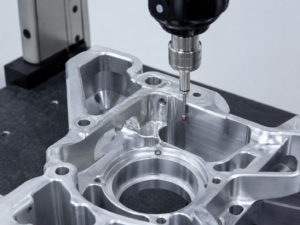
Some dimensions can be checked using standard gauges and conventional equipment. Others may require a coordinate measuring machine, specialist probes, optical equipment or custom fixtures. Designers should consider:
- Whether measurement probes can reach the feature
- Whether the feature is visible and accessible
- Whether a suitable reference surface is available
- Whether the tolerance can be verified after assembly
- Whether a coating or finish will alter the measured condition
- Whether custom gauging may be required
- Whether the drawing identifies the required inspection stage
- Whether internal features need indirect verification
Inspection accessibility should be considered alongside cutter access. A feature that can be machined successfully may still be difficult to measure with sufficient confidence.
Standard Versus Non-Standard Aerospace Material Sizes
Material selection is normally driven by strength, weight, corrosion resistance, temperature performance and regulatory requirements. However, the specified material form and starting size can also affect availability, cost and lead time.
A component designed slightly larger than a commonly available bar, plate or billet size may require the next size up, increasing material waste and machining time. A non-standard thickness may need to be specially sourced or machined down before the component itself can be produced. Material-related DFM considerations include:
- Availability of the specified alloy and temper
- Standard bar, plate and billet dimensions
- Minimum order quantities
- Material certification requirements
- Rolling or grain direction
- Allowance for machining and workholding
- Availability across future production batches
- Suitability for heat treatment, anodising, plating or painting
- Potential distortion during material removal
Designers should not change an aerospace material specification solely for convenience. However, reviewing the intended starting stock with a supplier may reveal opportunities to reduce waste or avoid unnecessary procurement delays.
Designing Aerospace Components Around Available Tooling
Designing around available tooling does not mean restricting innovation. It means understanding how standard cutters, drills, taps, probes and workholding systems can be used to manufacture the component efficiently.
A feature that requires a bespoke tool may be entirely justified, particularly for repeat production. For prototype or low-volume work, however, specialist tooling can add cost and extend lead time. Tooling-related questions include:
- Can standard drill and reamer sizes be used?
- Are thread forms and pitches readily available?
- Does the corner radius suit a standard cutter?
- Can features be reached using rigid tooling?
- Are there unnecessary variations in hole or thread sizes?
- Will the tooling have sufficient clearance?
- Can the feature be machined without a custom angled tool?
- Is bespoke tooling justified by the expected production volume?
Standardising repeated features across a component or product family can also reduce tool changes, simplify programming and make future production more consistent.
Reducing CNC Machining Setups in Aerospace Production
Each time a component is removed, repositioned or transferred to another machine, additional time and process variation may be introduced. Some parts inevitably require multiple setups, but design decisions can sometimes reduce them.
Features placed on many different faces, angled holes and difficult-to-access surfaces may require additional fixtures or machine orientations. The number of setups for suitable components can be reduced with 5-axis CNC machining, although it does not eliminate every access or workholding constraint. Design choices that may reduce setups include:
- Grouping related features on accessible faces
- Avoiding unnecessary angled holes
- Providing suitable workholding areas
- Allowing access for multi-axis machining
- Designing features that can share common datums
- Minimising features that require manual repositioning
- Considering how the final setup will be held after most material has been removed
Reducing setups can improve dimensional relationships between features because more of the component can be completed from a common position.
Surface Finishes and Post-Machining Processes
Aerospace design for manufacture should include processes that occur after CNC machining. Anodising, plating, passivation, painting, heat treatment and non-destructive testing may affect dimensions, masking requirements and production sequencing.
A thread, bore or sealing face may need to be masked during finishing. A coating may add thickness to a dimensionally controlled surface. Heat treatment may create distortion that must be allowed for in the manufacturing route. Designers should specify:
- The required finish and governing standard
- Which surfaces must be coated
- Which areas must be masked
- Whether dimensions apply before or after finishing
- Any cosmetic or surface-condition requirements
- Whether conductivity or electrical contact areas must remain untreated
- Whether marking is required
- Any non-destructive testing requirements
Unclear finishing instructions can create delays while the manufacturer seeks clarification. A complete drawing and specification package helps suppliers plan machining, inspection and subcontract processes correctly.
Prototype Components Versus Repeat Aerospace Production
A design that is practical for one prototype may not be efficient for regular batch production. Conversely, investing in dedicated fixtures or special tooling may not be commercially sensible for a single development component.
Expected production quantities should therefore form part of the aerospace DFM discussion. The manufacturing approach may change as the requirement moves from prototype and new-product introduction into repeat production. For prototype work, priorities may include:
- Fast programming and setup
- Use of standard tooling
- Flexible workholding
- Rapid design feedback
- Avoiding unnecessary bespoke fixtures
For repeat production, priorities may include:
- Dedicated fixtures
- Reduced cycle time
- Automated probing
- Standardised inspection routines
- Tool-life management
- Repeatable material supply
- Controlled production documentation
Informing the supplier about likely future volumes allows them to recommend an approach that supports both the immediate requirement and potential scale-up.
When to Involve an Aerospace Manufacturing Supplier
The best time to involve a manufacturing supplier is usually before the design is frozen. At this stage, changes can often be made with relatively little disruption. Once drawings have been approved, assemblies designed around them and qualification activity has begun, even a small change may require extensive review.
An early supplier conversation can help identify issues relating to tooling, inspection, workholding, material size, finishing and realistic tolerances. Useful stages for supplier involvement include:
- During early component concept development
- Before releasing drawings for quotation
- Before finalising tolerance schemes
- When selecting materials and starting stock
- Before committing to a difficult internal feature
- When moving from prototype to repeat production
- When an existing component has recurring quality or lead-time problems
- Before freezing a design for qualification
The supplier should understand that the aim is to support the design intent, not to redesign the component without technical justification.
What to Include in an Aerospace DFM Review
A useful DFM review requires more than a simplified model. The manufacturer needs enough information to understand the component’s function, critical requirements and production context. The information supplied may include:
- A 3D CAD model
- A controlled engineering drawing
- Material specification
- Required quantity
- Expected future batch sizes
- Critical characteristics
- Surface finish requirements
- Heat treatment or coating specifications
- Inspection and reporting requirements
- Mating component information where appropriate
- Known areas of design concern
- Target delivery requirements
The more complete the information, the more useful the manufacturing feedback is likely to be.
Common Aerospace Design for Manufacture Questions
Design engineers do not need to know every detail of the machining process, but asking the right questions can reveal potential issues before production begins. A collaborative DFM review should focus on practical risk rather than simply asking whether the part is possible to manufacture. Useful questions include:
- Are any features particularly difficult to machine?
- Which dimensions will have the greatest effect on cost?
- Are the internal radii suitable for standard tooling?
- Can all controlled features be inspected?
- Is the datum structure practical?
- Will the selected material size be readily available?
- Are there areas likely to distort during machining?
- Could any setup be removed through a design change?
- Are finishing allowances and masking requirements clear?
- Would the design remain practical at higher batch quantities?
- Are any tolerances tighter than the functional requirement?
- Are there risks that could affect repeatability or lead time?
These questions help turn the quotation process into a technical discussion rather than a simple price comparison.
Aerospace Design for Manufacture Without Compromising Performance
Good DFM supports aerospace performance by reducing avoidable process risk. It does not mean removing important features, relaxing critical tolerances or substituting materials without engineering approval.
The strongest outcomes are achieved when the design team explains why a requirement matters and the manufacturing team explains how it affects production. This allows both parties to explore alternatives without losing sight of function, safety or compliance.
For example, a manufacturer may suggest a larger internal radius, but the designer may confirm that the existing radius is necessary for component clearance. The outcome may then be to retain the feature while planning the correct tooling, machining method and lead time.
A collaborative process allows manufacturing difficulty to be understood and managed rather than discovered after the design has been released.
Choosing a Supplier for Aerospace DFM Support
An aerospace machining supplier should be able to provide practical feedback based on relevant component, material, machining and inspection experience. The quality of the review depends on the supplier’s ability to understand both the drawing and the production route.
When assessing DFM support, consider whether the supplier can demonstrate:
- Experience with relevant aerospace materials
- Multi-axis CNC machining capability
- Appropriate inspection and measurement equipment
- Understanding of drawing and revision control
- Traceable material and process documentation
- Experience with prototypes and repeat batches
- Access to approved finishing and testing processes
- Clear technical communication
- A structured approach to design queries and problem escalation
Certification may form part of the supplier assessment, but the practical value of DFM support comes from detailed manufacturing knowledge and open communication.
Aerospace Design for Manufacture Checklist
A final aerospace design for manufacture review can help ensure that production risks have been considered before the drawing is approved. The review should involve the appropriate design, manufacturing and quality stakeholders. Before freezing the component design, check that:
- Critical functional features are clearly identified
- Tolerances match the actual engineering requirement
- Internal corner radii permit practical tool access
- Deep pockets have been reviewed
- Thin walls can be supported and machined reliably
- Datum features are stable and accessible
- Inspection probes or gauges can reach controlled features
- Standard material sizes have been considered
- Thread and hole sizes are practical
- Unnecessary tool changes have been avoided
- Workholding areas are available
- Post-machining finishes are fully specified
- Dimensions are identified as pre-finish or post-finish where necessary
- Production quantities have been shared with the supplier
- The design has been reviewed before release
A checklist cannot replace engineering judgement, but it can help ensure that common manufacturing issues are not overlooked.
Improving Aerospace Component Manufacturability
Aerospace design for manufacture helps engineering teams develop components that are not only capable of meeting their intended function but can also be machined, inspected and repeated reliably.
Internal corners, deep pockets, thin walls, tolerances, datums, materials and tooling all influence the manufacturing route. Addressing these factors during the design stage can reduce unnecessary machining time, improve inspection access and create a more predictable transition from prototype to repeat production.
The most effective DFM process is collaborative. Design engineers retain control of the functional requirements, while manufacturing engineers provide practical input on machining, workholding, tooling, inspection and production risk.
Ask our engineers to review your component before the design is frozen. Send us an RFQ or a Quick Message today.