Machined plastic parts sit in a useful middle ground between metal components, injection moulded plastics, and additive manufacturing. They can be produced quickly from engineering-grade polymers, hold tight tolerances when designed sensibly, and offer material properties that are difficult (or expensive) to replicate in metal – such as electrical insulation, low friction, corrosion resistance, chemical compatibility, and very low weight.
If you’ve ever specified a component for aerospace, medical devices, electronics, or industrial equipment, you’ve likely encountered the same question: should this be metal, moulded plastic, printed polymer… or a machined plastic part? The “right” answer depends on function, environment, tolerance, volume, and quality requirements. This article unpacks the decision in a practical way: how machined plastic parts are made, which materials perform best, what designers can do to avoid common pitfalls, and how quality systems like ISO 9001 and AS9100 shape the way critical components are controlled and documented.
What Counts as Machined Plastic Parts?
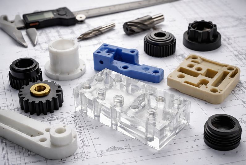
Machined plastic parts are components cut from solid polymer stock – bar, plate, tube, or billet – using subtractive processes such as CNC milling, turning, drilling, reaming, and threading. Instead of creating the shape in a mould (injection moulding) or building it layer-by-layer (3D printing), machining removes material to produce the final geometry.
Typical examples include:
- Bushes, bearing pads, wear strips, and guides
- Insulators, standoffs, and electrical carriers
- Valve seats, seals (non-elastomeric), and fluid-handling manifolds
- Lightweight housings, covers, and spacers
- Precision fixtures, jigs, and sacrificial tooling
- Medical device components and laboratory parts
- Aerospace brackets, supports, and ducting-related elements where metals are unnecessary or undesirable
The appeal is straightforward: you can start with high-performance plastics (like PEEK, PTFE blends, PEI/Ultem, PPS, PVDF) and produce accurate, repeatable parts without the time and cost of tooling.
Why Choose Machining Over Moulding or Printing?
Machined plastic parts aren’t automatically “better”, but they’re better for certain constraints. Here’s where machining usually wins.
Lower up-front cost and faster iteration
Injection moulding typically requires tooling. Even modest tools can be expensive and time-consuming, especially when you factor in design validation cycles. Machining often allows prototypes and low-to-medium production volumes with minimal setup and very fast revisions.
Higher-performance materials without process compromises
Many high-end polymers can be moulded, but moulding may require careful gating, drying, and process control. Some grades and filled materials are more practical to machine than to mould, particularly in lower volumes.
Dimensional control for low and medium volumes
For precision features – flatness, perpendicularity, concentricity, controlled bores, and critical datum relationships – machining can be highly effective, provided the part is designed with polymer behaviour in mind.
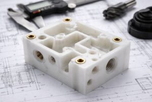
Better for thick sections, complex features and inserts
Moulding thick parts can introduce sink marks, voids, and warpage. By CNC machining parts it is possible create thick, robust geometries and add metal inserts, helicoils, bushings, or bonded subcomponents without mould complexity.
Printing is great, but has limits
3D printing excels in early prototyping and complex shapes, but can struggle with anisotropy (directional strength), surface finish, and tight tolerances. Many engineers use printing to validate shape, then switch to machining for functional testing and production-ready performance.
Understanding Plastic Behaviour
A lot of disappointment with machined plastic parts comes from treating plastics like “lightweight aluminium.” They aren’t. Polymers are viscoelastic: they respond to load, temperature, time, and even humidity in ways metals largely don’t. The good news is that once you account for these behaviours, plastics can be extremely predictable and reliable. The key is to think in terms of service conditions (temperature range, load duration, fluids, and assembly method) rather than just room-temperature dimensions on a drawing. The four differences below are the big ones that influence tolerancing, fit and long-term performance.
Thermal Expansion Is Larger
Most engineering plastics expand and contract far more than aluminium or steel as temperatures change. That matters if your part has to locate precisely, seal against another component, or maintain a sliding fit over a temperature range. A bore that measures perfectly at 20°C can tighten noticeably at low temperature or become loose at higher temperature – especially if it mates with a metal shaft that expands at a different rate. In assemblies, this mismatch can create unexpected friction, noise, or even stress cracking if the joint becomes over-constrained.
Practical takeaway: define the operating temperature range early and design fits accordingly. Where thermal variation is significant, consider allowing clearance, using compliant features, choosing a more dimensionally stable polymer (or a filled grade), or designing the interface so the plastic can “float” rather than being locked in multiple directions.
Creep Matters
Unlike metals, many plastics will creep – they slowly deform under a constant load. This doesn’t necessarily mean the part is “failing,” but it can change how the part behaves over time. For example, a plastic bracket might gradually relax under a sustained clamping load, reducing preload and causing a joint to loosen. A pressed-in bushing might lose interference over months. A plastic spacer in compression might shorten slightly, altering alignment. Creep is accelerated by higher temperatures and higher stress, so what looks fine on day one can drift out of spec after weeks or months in service.
Practical takeaway: avoid relying on plastics to hold long-term preload without help. Spread loads with washers or flanges, reduce stress concentrations, and consider inserts or metal load paths for bolted joints. If sustained load at temperature is unavoidable, select polymers with stronger creep resistance (often higher-performance materials or filled grades) and design the geometry to keep stresses low.
Moisture Absorption Can Change Dimensions
Some plastics – most notably nylon (polyamide) – absorb moisture from the environment. This can cause measurable dimensional change and can also affect mechanical properties (often making the material tougher but less stiff). The impact depends on humidity, exposure time, and part thickness. A thin nylon part can equilibrate relatively quickly; a thick section can change more slowly and unevenly. For tight-tolerance components, this moisture-driven movement can be the difference between a smooth sliding fit and a binding one, or between an accurate locating feature and one that drifts.
Practical takeaway: if dimensional stability is critical, either choose a low-absorption material (such as acetal) or design the nylon component so dimensional change doesn’t affect function. In some cases, you may specify conditioning requirements, store parts in controlled packaging, or measure parts in a consistent state, but the simplest approach is usually to design for the reality that nylon moves.
Heat from Cutting Can Cause Local Distortion
Plastics don’t conduct heat as well as metals, which means heat generated during machining can stay concentrated near the cutting zone. If tooling is dull, feeds are too light (causing rubbing), or chip evacuation is poor, the surface can soften, smear, or distort. Thin walls are especially vulnerable: they can flex during machining and then “spring” after the cut, or warp as temperatures equalise. Certain materials also tend to create stringy chips, which can re-cut and add even more heat. This is why two shops can machine the same polymer and get very different results – process strategy and tooling matter a lot.
Practical takeaway: machining plastics is its own discipline. Sharp tools, correct chip loads, stable workholding, and sensible toolpaths help prevent heat build-up. For higher-precision features, staged machining (roughing then finishing) and letting parts stabilise before final passes can improve consistency. Designers can help by avoiding overly thin unsupported walls and by adding radii and stiffness where possible.
Why This Isn’t a Problem (If You Design for It)
None of these behaviours make plastics “unreliable.” They just mean the design intent has to match the material reality. The best-performing machined plastic parts usually come from a simple mindset: don’t chase metal-like tolerances everywhere; instead, control what matters, allow movement where it doesn’t, and choose materials based on the real environment. When tolerances, fixturing approach, and polymer selection are considered together, plastics deliver very consistent performance – and often solve problems that metals can’t (corrosion, friction, weight, insulation) at the same time.
Common Materials Used for Machined Plastic Parts
Material selection is the foundation. Here are widely used options and where they shine.
Acetal (POM / Delrin)
Acetal is one of the most widely specified engineering plastics for machined plastic parts because it combines stiffness, low friction, and strong dimensional stability. It machines cleanly and is a reliable choice when you need accurate sliding fits, consistent bores, or repeatable parts without stepping up to premium polymers.
- Good dimensional stability, low friction, easy to machine
- Strong choice for gears, bushes, sliding components, precision spacers
- Generally a “go-to” for tight-tolerance machined plastic parts in general industrial applications

Nylon (PA6 / PA66)
Nylon is valued for toughness and wear performance, making it a great option for rugged, impact-prone components. It’s often chosen where parts see shock loads or abrasion, but designers should account for moisture-related dimensional change – especially in tighter tolerance assemblies.
- Tough, impact resistant, good wear properties
- Absorbs moisture (dimensions can shift), can be stringy to machine
- Good for rugged components where small dimensional changes are acceptable or can be accounted for
UHMW-PE
UHMW-PE is a classic “wear material” used where low friction and abrasion resistance matter more than tight dimensional control. It’s ideal for guiding, sliding, and protecting surfaces, although its softness means it can deflect during machining and under load if not supported.
- Extremely low friction, excellent abrasion resistance
- Softer and more prone to deflection under cutting loads
- Common for wear strips, guides, and sliding surfaces
PTFE (and filled PTFE)
PTFE is often selected when chemical resistance and lubricity are non-negotiable – particularly in sealing and aggressive fluid environments. It’s softer than most engineering plastics and can creep under load, so it’s best used with designs that don’t rely on tight interference fits or sustained compression unless a filled grade is specified.
- Best-in-class chemical resistance and low friction
- Very soft and prone to creep; tight tolerances can be challenging
- Filled PTFE (glass, carbon, bronze) improves wear and stability
Polycarbonate (PC)
Polycarbonate is a strong choice when you need impact resistance and toughness, including transparent parts where visibility matters. It can be sensitive to certain chemicals and stress effects, so machining strategy and end-use environment both need consideration to avoid cracking or crazing over time.
- High impact strength, transparent grades available
- Can stress-crack with some chemicals; machining requires care to avoid crazing
- Used for guards, covers, optical-ish components where clarity matters (sometimes acrylic is chosen for better optical clarity)
Acrylic (PMMA)
Acrylic is chosen primarily for excellent optical clarity and the potential for a very clean surface finish. It machines nicely for crisp edges and polished faces, but it’s more brittle than polycarbonate, so it suits parts that won’t see heavy impact or high clamping stress.
- Excellent clarity and surface finish potential
- More brittle than PC, chips cleanly but can crack if stressed
- Used for display components, light guides, lab items
PEI (Ultem)
PEI is a high-performance polymer known for maintaining strength and stiffness at elevated temperatures while offering good flame resistance. It’s commonly used for structural insulating components in demanding electrical or aerospace-adjacent environments where standard plastics soften too easily.
- High temperature performance, good stiffness, flame resistance
- Machines well with correct tooling
- Common in aerospace and electronics for insulative, high-temp parts
PPS
PPS is often specified for harsh environments because it combines temperature capability with excellent chemical resistance and stability. It’s a strong option for components exposed to aggressive fluids, heat, or repeated thermal cycling – particularly when you need a tougher, more stable alternative to commodity plastics.
- High temperature, chemical resistance, good dimensional stability
- More specialised; excellent in harsh chemical/thermal environments
PEEK (and filled PEEK)
PEEK sits near the top tier for machined plastic parts, offering exceptional mechanical performance, temperature capability, and chemical resistance. It’s frequently used when a polymer must behave reliably in demanding service conditions and where switching away from metal delivers benefits like weight reduction, corrosion resistance, or electrical isolation.
- Premium mechanical performance at high temperature
- Excellent chemical resistance, fatigue performance, and stability (relative to many plastics)
- Common in aerospace, medical, oil & gas – especially where metal is problematic (weight, corrosion, electrical isolation)
PVDF / PCTFE (specialist fluoropolymers)
PVDF and PCTFE are typically chosen for specialist chemical, purity, and temperature requirements rather than general mechanical strength. They appear often in fluid handling, laboratory, and semiconductor-related applications where material compatibility, cleanliness, and predictable behaviour in extreme conditions drive the specification.
- Chosen for chemical compatibility, purity, or low-temperature performance
- Often used in semiconductor, laboratory, and fluid handling
Tip: When specifying machined plastic parts, always name the exact grade if performance is critical (including whether it’s filled, glass/carbon content, and any compliance requirements).
How Machined Plastic Parts Are Made: Processes and Practical Realities
Machining plastics looks similar to machining metals from the outside – CNC mills, lathes, drills, and inspection equipment – but the process choices are often different. Plastics are more sensitive to heat, they can deflect under clamping and cutting forces, and some materials will “relax” after machining as internal stresses redistribute.
Success with machined plastic parts is usually less about brute rigidity and more about sharp tooling, good chip evacuation, sensible cutting parameters, and a machining plan that balances accuracy with stability. The following processes are the core building blocks, with the practical realities that influence quality and repeatability.
CNC milling
CNC milling is the workhorse process for prismatic and multi-featured parts – think housings, pockets, manifolds, brackets, plates, covers, and complex 3D surfaces. The main challenge in plastics is avoiding heat build-up and preventing thin features from flexing during cutting. When heat rises, some polymers smear rather than cut cleanly, and when features flex, they can spring back and leave you with tapered walls or out-of-flat faces.
In practice, good plastic CNC milling often uses toolpath strategies that keep the tool moving, clear chips efficiently, and avoid repeatedly skimming the same area. Roughing and finishing passes are especially valuable: you remove bulk material in a stable way, then take lighter finishing cuts once the part has “settled.” Workholding also matters more than people expect – over-clamping can distort a plate, and vacuum or soft jaws may be preferable for delicate geometries.
Plastics often prefer:
- Sharp cutters (polished flutes can help)
- Appropriate chip loads to avoid rubbing and heat build-up
- Toolpaths that minimise dwell and repeated passes that “heat soak” thin walls
CNC Turning
CNC turning is ideal for rotational components such as bushes, rollers, spacers, insulators, threaded parts, and certain seal geometries. Compared with metals, plastics can behave “springy” on the lathe: they may deflect away from the tool during the cut and then recover afterwards, which can affect diameter control and surface finish. This is especially noticeable on thin-walled rings, long slender parts, or softer materials like PTFE and UHMW-PE.
Chip control is another reality of turning plastics. Some materials create long, stringy swarf that can wrap around the part or tool, affecting finish and causing heat. Tool geometry, feeds, and a plan for clearing chips become important—not just for quality, but for process stability in production runs. In many cases, it’s better to take confident cuts that form clean chips than to “tickle” the surface with ultra-light passes that generate heat by rubbing.
With turning, plastics can:
- Deflect under tool pressure
- “Spring” slightly after the cut
- Form stringy chips (material dependent)
Good workholding and sharp geometry matter.
Drilling, Reaming and Boring
Holes in plastics can be deceptively tricky, particularly when you need accurate size, roundness, or positional control. Standard metal-cutting drills can grab, wander, or generate enough heat to soften the surface—leading to poor finish, bell-mouthing, or a hole that measures differently depending on how it’s gauged. The risk increases in softer plastics, deep holes, and small diameters, where chip evacuation is harder.
For precision bores, machining strategy matters as much as the tool. Drilling is often used to create a pilot hole quickly, then boring or reaming is used to bring the feature into tolerance with better control. Some polymers (notably nylon) can “relax” after machining, so the hole may drift slightly as internal stress redistributes – one reason staged machining and consistent measuring conditions are helpful. Also, press fits in plastics need careful thought: too much interference can crack the part or create high residual stress; too little can relax over time.
For precision bores:
- Boring/reaming gives better control than drilling alone
- Consider post-machining relaxation (especially in nylons and softer plastics)
- Use sensible tolerances matched to function (press fits in plastics are not the same as press fits in steel)
Threading and Inserts
Threads can be cut directly into many plastics, but long-term durability depends on how the thread is loaded, how often it’s assembled, and whether the polymer is prone to creep. A thread that holds fine in light-duty service may strip when repeatedly torqued, or it may slowly lose clamp force under constant load – especially at elevated temperatures. That’s why many “good” plastic designs treat the plastic thread as a convenience feature, and use inserts where the joint is structural or frequently serviced.
Thread form choice is important. Coarser threads generally provide better strip resistance because they leave more material between thread roots. Thread-forming taps can produce strong threads in suitable materials by displacing rather than cutting material, but they need correct pilot sizing and controlled process parameters. For higher loads, repeated assembly, or tight torque requirements, inserts are often the most reliable route – helical inserts, heat-set inserts, or moulded-in inserts (where applicable). In critical joints, adding a metal bushing or insert to carry clamp load prevents creep and protects the plastic from compressive damage.
Options:
- Coarse threads often outperform fine threads in plastics
- Thread-forming taps can work well in some materials
- Helical inserts or moulded-in/heat-set inserts provide robust threads for repeated assembly
- For high-load joints, a metal insert or bushing is often the most reliable approach
Tolerances and Surface Finish: What’s Realistic?
Many machined plastic parts can hold impressively tight tolerances, but “tight” should always be tied to function. Unlike metals, polymers are more sensitive to temperature, time under load, and even storage conditions. When tolerances are applied everywhere “just to be safe,” the result is usually higher cost, longer lead times, and increased scrap risk – without any real improvement in assembly performance. A better approach is to control the features that truly matter (datums, fits, sealing faces) and allow more freedom where it won’t affect function.
Thermal Expansion and Measurement Temperature
Plastics expand and contract more than metals, so a dimension verified at one temperature may not hold at another. A bore that is perfect at 20°C can become meaningfully tighter at lower temperatures or looser at higher ones, especially when paired with metal mating parts that move at a different rate. This isn’t only an “in service” issue – inspection and handover can be affected too. If a supplier measures parts in a warm workshop and you measure them in a cooler goods-in area, you can see differences that look like out-of-tolerance conditions even when the machining was correct.
What to do about it:
- Specify theoperating temperature range for critical fits and sealing features.
- Where temperature swing is unavoidable, design clearance into non-critical relationships and avoid over-constraining the part.
- Consider more dimensionally stable materials (or filled grades) for tight interfaces.
- Align measurement conditions where possible (agree a reference temperature or inspection method for critical features).
Elastic Recovery After Machining and Clamping
Plastics can deform slightly under cutting forces and workholding, then “spring” back once the tool passes or the clamp is released. This can show up as subtle taper on walls, a bore that gauges differently depending on measurement technique, or a flat face that relaxes out of perfect flatness after unclamping. Thin walls, long unsupported features, and softer polymers are the usual culprits. Even when the machining is accurate, the part’s temporary deformation during manufacture can lead to geometry that doesn’t quite match expectations once it’s free.
What to do about it:
- Avoid very thin, unsupported walls where tight tolerances are required.
- Use sensible datum structures so the part can be held consistently without distortion.
- Apply staged machining (rough, then finish) on critical faces and bores.
- For inspection, use methods that don’t “squeeze” the part (light measuring force, correct fixturing).
Creep and Long-term Dimensional Change Under Load
Creep is a time-dependent change in shape under sustained stress. A plastic part can be perfectly in tolerance at inspection and still drift in fit or alignment after weeks or months of constant load – especially at elevated temperatures. This matters for press fits, bolted joints, and alignment features. For example, a plastic spacer in compression can shorten slightly, a clamp load can relax, or a locating feature can shift enough to affect repeatability. In assemblies that depend on preload or precise long-term positioning, creep is often the hidden cause of “mystery loosening” or gradual misalignment.
What to do about it:
- Reduce stress by increasing contact area (flanges, washers, larger bearing surfaces).
- Avoid relying on plastic alone to hold preload; use inserts, bushings, or metal load paths for high-stress joints.
- Choose materials with better creep resistance for sustained-load applications (often higher-performance polymers or reinforced grades).
- Design fits so function is maintained even if small long-term movement occurs.
Moisture Absorption and Humidity-driven Movement
Some plastics absorb moisture from the air, and that moisture uptake can change dimensions. Nylon is the most common example: it can be tough and wear-resistant, but its size can shift with humidity and time. That shift may be small in absolute terms, but it becomes critical when parts are designed with minimal clearance, when they must maintain precision alignment, or when they are measured in different environmental conditions across the supply chain. Moisture can also affect stiffness and friction behaviour, which may influence performance in sliding interfaces.
What to do about it:
- If dimensional stability is critical, consider low-absorption alternatives (e.g., acetal) or a different polymer family altogether.
- Where nylon is needed for toughness, design with clearances that tolerate expected movement.
- Define storage/conditioning expectations if they materially affect inspection and assembly.
- Be explicit on drawings about which dimensions are truly critical versus nominal.
Surface Finish: Realistic Requirements for Plastics
Surface finish is often specified as a habit carried over from metal parts, but plastics should be driven by function: friction, sealing, cleanliness, optics, and appearance. Very smooth finishes can reduce friction on sliding components, but they can also reveal machining marks differently across polymers, and some parts perform better with a controlled texture (for example, to retain lubricant or avoid sticking). Overly tight surface finish requirements can add time and cost – especially if they force polishing steps – so they should be targeted only where needed.
What to do about it:
- Call out finish requirements only on functional faces (sealing lands, bearing surfaces, optical faces).
- Avoid blanket “mirror finish everywhere” unless the application truly needs it.
- If a part will be bonded, sealed, or printed on, specify surface preparation requirements rather than just Ra numbers.
Design for Manufacturability (DFM) for Machined Plastic Parts
If you want reliable, repeatable machined plastic parts, design choices matter just as much as machining skill. Plastics respond differently to cutting forces, clamping pressure, and heat, so a geometry that machines perfectly in aluminium can distort, chatter, or “move” when produced in polymer. Good DFM reduces those risks by making the part easier to hold, easier to cut without heat build-up, and less likely to relax after machining. The payoff is tangible: better dimensional consistency, higher yields, shorter lead times, and a drawing that communicates what truly matters (rather than forcing unnecessary tight controls everywhere).
Keep Walls and Webs Sensible
Thin walls and narrow webs are common sources of variation in machined plastics because they flex during cutting and can relax afterwards as internal stresses equalise. Even if the part measures correctly immediately after machining, thin sections can warp slightly over time, especially if stock removal is uneven or the component sees temperature changes. Where thin walls are unavoidable, the goal is to build stiffness into the design so the geometry stays stable during machining and in service.
- Add ribs where possible
- Avoid deep pockets with thin floors
- Use gradual transitions rather than abrupt steps
Use Generous Internal Radii
Internal corners drive tool choice. Small radii force small cutters, which are less rigid, generate more heat, and increase cycle time – especially in tough, heat-sensitive polymers. Larger internal radii make machining more efficient and produce more consistent results, because the tool can maintain healthier feeds and chip loads without rubbing. They also improve part strength by reducing stress concentrations, which is particularly valuable in plastics where sharp corners can become crack initiation points under load or impact.
- Improve strength (reduce stress concentration)
- Reduce machining time
- Improve surface finish consistency
Avoid Long, Slender Features Without Support
Slender posts, thin arms, and long fins can be difficult to machine in plastics because the material can deflect and chatter under tool pressure. That deflection can create tapered features, poor surface finish, or dimensions that vary depending on the direction of cutting. In softer polymers, the issue can be even more pronounced. The most manufacturable designs either shorten unsupported lengths, increase section thickness, or provide temporary stiffness during machining so the final geometry is reached predictably.
- Add temporary support features (later removed)
- Break the operation into staged machining
- Consider alternative geometry that provides stiffness during cutting
Think About Workholding Early
Workholding is often the hidden factor behind inconsistent plastic parts. Plastics can distort under clamping load, and if the part is thin or wide, it may “dish” or bow – then spring back when released. If the design doesn’t include good reference faces or balanced geometry, it becomes harder to fixture consistently, and that drives variation across batches. Designing with workholding in mind helps the machinist locate the part repeatably with minimal stress, which improves accuracy without needing heroic inspection or overly tight process controls.
- Flat reference surfaces
- Symmetry or balanced stock removal
- Optional sacrificial tabs or machining allowances
Be Realistic About Press Fits and Snap Fits
Press fits and snap fits are absolutely possible in machined plastics, but they need polymer-specific thinking. Press fits can relax over time due to creep, particularly under sustained load or elevated temperature, and too much interference can split thin walls or create high residual stress. Snap fits can work very well, but only when the chosen polymer has the right strain capability and fatigue resistance for repeated deflection. Designing these features with appropriate lead-ins, controlled interference, and stress-relieving geometry makes them far more reliable.
- Add lead-in chamfers and avoid sharp stress risers
- Use interference values appropriate to the polymer (not metal rules-of-thumb)
- Choose materials with suitable fatigue/strain behaviour for snap features
Heat, Stress and Distortion: Why Plastics “Move”
Plastics can “move” during machining for two main reasons, and both are tied to the fact that polymers respond more readily than metals to temperature and stress changes. Understanding these two mechanisms helps explain why a part can look perfect on the machine, then measure slightly differently once it cools, is unclamped, or sits for a short period.
Heat Input from Cutting
Plastics don’t conduct heat as efficiently as metals, so a lot of the heat generated at the cutting edge stays localised in the part and the chip. If cutting parameters are too gentle (causing rubbing rather than cutting), if chips aren’t cleared effectively, or if a tool is dull, the surface temperature can rise quickly. That can temporarily soften the material, leading to smearing, slight dimensional growth during machining, or distortion in thin features. Once the part cools and the heat dissipates, those areas can shrink back unevenly, which shows up as minor warping, waviness, or size drift – especially on wide, thin parts and deep-pocketed geometries.
Release of Internal Stresses (from Extrusion, Casting or Previous Machining)
Plastic stock often contains residual stresses from how it was made – extruded bar, plate, or cast billet can carry “locked-in” stress from cooling, pulling, and forming. When you machine away material, you remove that stressed outer layer and change the balance of forces within the stock. The part can then relax into a new shape, sometimes subtly and sometimes noticeably, particularly when large amounts of material are removed from one side or when the geometry is thin and asymmetrical. This is also why a rough-machined part may shift slightly before finishing: the first operation can release stress, and the second operation needs to be planned with that relaxation in mind.
Mitigations include:
- Selecting stable stock (and reputable material supply)
- Using sharp tools, proper chip loads, and avoiding rubbing
- Controlling coolant/air blast to remove chips and heat
- Machining in stages (roughing, rest, finishing) for stability
- In some cases, annealing/stress relieving stock before final finishing (material dependent)
This is one reason experienced shops treat machined plastic parts differently to aluminium or stainless work. Even when the CAD is identical, the process plan often changes.
Secondary Operations and Finishing
Machined plastic parts often need secondary steps to meet real-world requirements—not because the machining is incomplete, but because performance, cleanliness, identification, and assembly demands go beyond raw geometry. These finishing operations can have a big impact on how a part fits, seals, wears, and survives in service, so it’s worth calling them out clearly where they matter.
Deburring
Plastics can leave fine “feathers” or raised edges around holes, slots, and milled pockets. Careful deburring prevents these from affecting assembly, scratching mating parts, or creating leak paths on sealing faces – especially where O-rings, gaskets, or close sliding fits are involved.
Polishing
Optical, cosmetic, or low-friction surfaces may need polishing to reduce visible tool marks and improve performance. Acrylic and polycarbonate often benefit when clarity is important, while materials like PEEK may be polished for smoother bearing or wear contact depending on the application and required finish.
Cleaning
Many sectors require controlled cleaning to remove chips, dust, coolant residue, and handling contamination. Medical, aerospace, semiconductor, and fluid-handling applications may also specify clean packaging to prevent recontamination and to protect sensitive sealing or mating surfaces.
Marking
Parts may need identification for traceability, orientation, or assembly control. Options include laser marking, engraving, or ink marking, with the best choice depending on the polymer, surface finish, readability requirements, and any compliance rules around contamination or material integrity.
Bonding/Welding
Some assemblies are produced by bonding or welding plastic components rather than machining a single piece. Solvent bonding is common for acrylic, ultrasonic welding can work well for compatible thermoplastics, and mechanical fastening is often used where serviceability or dissimilar materials are involved.
ESD Requirements
For electronics and sensitive assemblies, parts may need dissipative materials and controlled handling to prevent static build-up. This can extend beyond material choice to include ESD-safe machining practices, inspection handling, and packaging that maintains ESD protection through shipping and storage.
If any of these matter, specify them explicitly; don’t assume “standard” handling matches a regulated or contamination-sensitive application.
Quality control: ISO 9001 and AS9100 for machined plastic parts
Quality requirements vary widely. A nylon spacer for a factory jig doesn’t need the same controls as a PEEK insulator flying on an aircraft. This is where quality management systems and documentation expectations enter the picture.
ISO 9001: The Baseline Quality Management System
ISO 9001 focuses on consistent processes: document control, calibration, training, corrective actions, supplier management, and continual improvement. For many machined plastic parts, ISO 9001-level controls are the practical baseline – especially where traceability, inspection discipline, and repeatable process matter.
AS9100: Aerospace-focused Controls On Top of ISO Principles
AS9100 builds on ISO 9001 with additional aerospace requirements: stronger risk management, product safety considerations, counterfeit part prevention, tighter supplier controls, and deeper traceability and change management. In practice, an AS9100 machining standard often implies:
- More robust traceability expectations (material lots, process records)
- Stronger control of special requirements and documentation
- First Article Inspection (FAI) packages when required by customer or contract
- Clear handling of nonconformances and configuration control
For organisations that support aerospace programmes, it’s common to see machined plastic parts produced under AS9100 governance even when the part itself is “just plastic” – because the system-level risk, compliance, and traceability still apply.
As an example of how this plays out in real machining environments, UK manufacturers such as Tarvin Precision operate with ISO 9001 and AS9100-aligned approaches for different customer needs, which influences everything from job travellers to inspection records and material certification handling. Mentioning this isn’t about sales, it’s simply a reflection that the same polymer component can require very different controls depending on where it’s used and what the contract demands.
Inspection Methods That Matter for Plastics
Inspection for machined plastic parts often includes the “usual” dimensional checks – micrometers, bore gauges, height gauges, CMM, optical measurement—but plastics introduce a few extra wrinkles:
Measuring Force Matters
Many plastics will deflect slightly under point contact, so heavy-handed measuring can “squeeze” a dimension smaller than it really is. This is especially noticeable on thin walls, small diameters, and softer polymers. Using consistent, light measuring pressure (and the right type of gauge) helps ensure readings reflect the true part geometry rather than the force applied.
Temperature Control Matters
Plastics expand and contract more than metals, so even modest temperature differences between the part, the gauge, and the inspection area can shift readings. Letting both the component and measuring equipment stabilise to the same ambient conditions reduces disputes and improves repeatability—particularly for tight-tolerance features like bores, thicknesses, and mating interfaces.
Surface Compliance
Softer materials can “give” under contact, and surface texture can affect how tools seat on the part. Without the right method—proper anvils, correct gauge type, stable fixturing, and repeatable measurement points—you can get misleading results that vary from inspector to inspector. This is why defined inspection plans and consistent technique matter more with plastics than many people expect.
Thread Verification
Go/no-go gauges are a practical way to verify threads, but plastic threads behave differently than metal ones. Threads can be more sensitive to burrs, elastic recovery, and slight deformation during gauging, and long-term performance is influenced by creep and repeated assembly. Where threads are critical, it’s often worth pairing gauging with clear torque limits, insert specifications, or functional fit checks in the actual mating hardware.
If a part is tied to regulated use (aerospace, medical, semiconductor), inspection records and calibration traceability become just as important as the dimensions themselves.
Applications: Where Machined Plastic Parts Excel
Machined plastic parts are often chosen when designers need a combination of precision, fast turnaround, and polymer-specific benefits like corrosion resistance, electrical insulation, low friction, or weight reduction. They’re especially valuable in sectors where material performance is tightly linked to the environment—temperature, chemicals, cleanliness, and long-term reliability—because machining allows tight control without the cost and lead time of tooling.
Aerospace and Defence
In aerospace and defence, machined plastic parts are frequently used to reduce weight, prevent corrosion, and provide insulation or wear performance in assemblies where metal isn’t necessary. Material selection is typically driven by temperature capability, outgassing behaviour, and consistent performance under vibration and thermal cycling.
- Lightweight brackets, supports, insulators, and wear components
- Cable routing hardware, protective covers, non-structural items
- High-temp polymers (PEI, PEEK, PPS) and low-outgassing/chemical-resistant selections
Medical and Life Sciences
Medical and life science applications often prioritise cleanliness, repeatability, and material compatibility with sterilisation or controlled environments. It is common to choose scientific CNC machining for prototypes and lower volumes, as well as for precision fixtures and components where performance and traceability matter more than unit cost at scale.
- Imaging equipment components, instrument parts, lab fixtures
- Biocompatible or sterilisation-compatible polymers (application-specific)
- Cleanliness and traceability often dominate the requirements
Semiconductor and Electronics
Semiconductor and electronics environments demand tight control of contamination, chemical compatibility, and in many cases electrostatic behaviour. Machined plastic parts can provide high-purity flow paths, precision carriers, and insulating structures while meeting strict handling and cleanliness expectations.
- High-purity polymers (PVDF, PCTFE), chemical resistance
- ESD-safe materials and handling
- Complex manifolds and precision carriers
Industrial and Automation
In industrial machinery and automation, machined plastic parts are widely used as wear and guide components, change parts, and fixtures – often because they reduce friction, noise, and maintenance compared to metal-on-metal contact. Speed of replacement and the ability to iterate designs quickly can be as important as the initial manufacture.
- Wear strips, guides, change parts, fixtures
- Low-friction and high-wear materials (UHMW-PE, acetal)
- Rapid replacement and iteration are often key value drivers
Fluid Handling and Chemical Processing
Fluid handling applications often come down to material compatibility first: the polymer must withstand the chemical, temperature, and pressure conditions without swelling, cracking, or contaminating the system. Machining is a practical route for manifolds, valve components, and bespoke geometries where sealing faces and internal flow paths need controlled accuracy.
- Valve seats, pump components, manifolds
- Chemical compatibility is often the primary selection driver (PTFE, PVDF, PEEK)
Cost Drivers and Lead-time Drivers (What Actually Changes the Quote)
If you’re trying to control cost and lead time for machined plastic parts, these factors usually dominate. Most surprises on quotes come from material choice, how much stock has to be removed, and how much time is required for inspection, finishing, and documentation – often more than the “cutting time” people assume is the main driver.
Material Cost and Availability
Premium polymers like PEEK, PEI, PPS, and specialist fluoropolymers can carry high raw material costs, and availability can be lead-time sensitive depending on grade, size, and certification needs. If you need a specific filled grade, colour, or compliance requirement, sourcing can become a meaningful part of the schedule.
Stock Size vs Finished Size
The bigger the starting billet compared with the final part, the more machining time you pay for – and the more expensive waste you generate. Heavy stock removal also increases the chance of stress release and distortion, which can add extra operations (roughing/resting/finishing) to hit final tolerances reliably.
Tight Tolerances Everywhere
Blanket tight tolerances increase cycle time, require more controlled machining strategies, and extend inspection time. They also raise scrap risk on plastics where temperature, deflection, and relaxation can influence final size, so it’s more cost-effective to keep tight limits only on truly functional features.
Deep Pockets and Small Internal Corners
Deep cavities, thin floors, and tiny internal radii force the use of small cutters and conservative toolpaths. That slows machining, increases the risk of chatter or heat build-up, and often requires additional finishing passes to achieve consistent geometry and surface quality.
Finishing/Cleaning/Packaging Requirements
Deburring, polishing, controlled cleaning, and special packaging can add significant labour and process time – especially for medical, aerospace, semiconductor, or fluid-handling parts. Clean packaging, surface protection, and contamination controls are often essential, but they should be specified clearly so they’re built into the plan and quote.
Documentation Expectations
Certificates of Conformance (CoCs), material certificates, inspection reports, and First Article Inspection (FAI/FAIR) packs add real time for verification, review, and record control. They can be absolutely worth it for regulated or high-risk applications, but they should be aligned to what the project actually needs rather than added by default.
A practical approach is to specify only what you truly need: define critical-to-function features, choose the right polymer grade, and align documentation to actual risk.
Common Pitfalls (And How to Avoid Them)
Most issues with machined plastic parts aren’t caused by “bad machining”—they come from a mismatch between polymer behaviour and the assumptions carried over from metal parts. The good news is that these pitfalls are predictable. A small amount of upfront thinking around environment, fit strategy, fastening, and tolerance intent will usually prevent rework, delays, and parts that perform well on the bench but drift in real service.
Choosing Nylon Without Accounting for Moisture
Nylon is tough and wear-resistant, but it absorbs moisture, which can change dimensions and stiffness over time. That can turn a perfect sliding fit into a tight one, or move a locating feature enough to affect repeatability—especially in humid environments or where parts are stored differently before assembly. If stability is critical, consider acetal, PPS, PEEK, or a moisture-stabilised nylon grade, or design the interface with clearance that tolerates expected movement.
Treating Plastics Like Aluminium
Plastics don’t like “metal logic” in cutting parameters. Too-light feeds can cause rubbing and heat, dull tools smear rather than cut, and poor chip evacuation can quickly distort thin features. The result is often local melting, stress, or subtle dimensional drift after cooling. Use tooling and speeds/feeds intended for polymers, keep cutters sharp, and plan toolpaths that maintain chip load and avoid heat soak—especially on deep pockets and thin walls.
Over-tightening Screws into Plastic
Plastic threads and bosses can fail in ways that metal designers don’t expect: stripping, cracking at stress risers, or gradual loss of clamp load due to creep. Even if the joint survives initial assembly, over-torque can leave hidden damage that shows up later as loosening or fracture. Use inserts for repeated assembly or higher loads, specify sensible torque limits, spread load with washers/flanges, and design bosses with adequate wall thickness and radii to avoid crack initiation.
Over-specifying Tolerances “Just in Case”
Tight tolerances everywhere don’t make plastic parts “safer”—they usually make them more expensive and harder to manufacture consistently. Polymers are sensitive to temperature and elastic recovery, so unnecessary tight limits increase inspection time and scrap risk without improving function. Use a clear datum strategy, tighten only the interfaces that truly control assembly or performance, and allow broader tolerances on non-critical geometry.
Ignoring Creep in Long-term Loading
A plastic part can be dimensionally perfect at inspection and still drift under sustained load, particularly at elevated temperature. This is common in press fits, clamped joints, and compression spacers where stresses are concentrated. If the part must hold alignment or preload over time, choose materials with stronger creep resistance (often higher-performance or filled grades), reduce stress by increasing contact area, and use inserts or metal load paths where the joint is structural.
A Specification Checklist for Machined Plastic Parts
If you want fewer surprises, include these items in your RFQ/drawing package:
- Material and exact grade (including filled/unfilled, colour, compliance needs)
- Critical features and functional tolerances (use GD&T if helpful)
- Surface finish requirements on functional faces only
- Thread strategy (machined thread vs insert; torque limits if relevant)
- Cleanliness and packaging requirements (especially medical/semiconductor/aerospace)
- Documentation: CoC, material certs, inspection report, FAI/FAIR if required
- Environmental conditions: temperature range, chemicals, UV exposure, wear expectations
- Quantity profile: prototype now, production later, expected annual usage
- Any special tests: leak/pressure test, dielectric test, fit verification, assembly checks
This kind of upfront clarity tends to reduce rework, shorten lead times and improve the odds that the first batch of machined plastic parts performs exactly as intended.
Making Machined Plastic Parts Work
Machined plastic parts are often the most direct route to high-performance polymer components with real engineering value. When you match the polymer to the environment, design the geometry for machining and long-term behaviour, and align tolerances and quality requirements to actual risk, you get parts that are lightweight, reliable, and repeatable.
And when programmes require deeper governance – traceability, controlled processes, documented inspection – machining under ISO 9001 and AS9100 quality systems provides a structured way to manage those expectations. In many UK supply chains, including environments like Tarvin Precision, that mix of standards is simply part of how teams ensure polymer components are controlled with the same discipline as metal parts when the application demands it.