Aluminium milling service providers are used to customers chasing a familiar mix of goals: low weight, good strength, high machinability, corrosion resistance, and a finish that looks as good as it performs. A good precision engineering company can deliver all of that – provided the process is set up around the supplied geometry, tolerances, surface requirements and end-use environment.
This guide explains how aluminium CNC milling works, what to include on an RFQ, which alloys to consider, and how to avoid common design and manufacturing pitfalls. It’s written for engineers, buyers, and project leads who want reliable outcomes – whether you’re ordering prototypes, small batches, or repeat production.
What an Aluminium Milling Service Actually Does
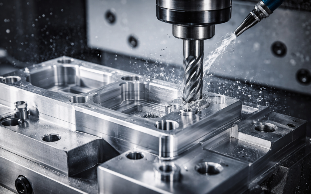
An aluminium milling service uses CNC milling machines to remove material from aluminium stock (plate, billet, bar, or extrusion) to create precise features like pockets, slots, bosses, contours, and datum surfaces. Milling differs from turning (lathe work) because the cutter rotates while the workpiece is held and positioned, allowing complex 2D and 3D shapes. Milling is often the best route when you need:
- Flatness and squareness control across multiple faces
- Pocketing and light-weighting features
- Mounting patterns, threaded holes, and precision bores
- 3D surfaces, blends, chamfers, and engraved identifiers
A capable supplier will combine the right tooling, feeds/speeds, workholding, and inspection approach so your aluminium parts meet spec consistently, not just “once off” for a single prototype.
CNC Aluminium Milling: How the Process Works in Practice
CNC aluminium milling is a balance of rigidity, chip control, heat management, and repeatability. Aluminium is typically “easy” to machine compared with many steels, but it has its own traps – especially around thin walls, burrs, and surface finish. A typical workflow looks like this:
- CAM programming to define toolpaths, stepovers, and cutting strategies
- Workholding selection (vise, fixture, vacuum, soft jaws) to prevent movement and distortion
- Roughing to remove bulk material efficiently while managing cutting forces
- Semi-finishing and finishing to meet surface finish and tolerance requirements
- Deburr and edge condition control to remove sharp edges and functional burrs
- Inspection using calibrated tools and (where appropriate) CMM or probing routines
When a shop like Tarvin Precision discusses aluminium CNC milling, the focus is usually on manufacturability and stability – how to maintain datums across setups, how to stop thin features “singing” under load, and how to protect critical surfaces from handling marks, rather than simply running a program and hoping for the best.
Precision Aluminium Milling: What Tolerances Are Realistic?
Precision means different things depending on part size, geometry, and measurement method. A good aluminium milling service will help you set tolerances that are functional but not unnecessarily expensive. In general, tight tolerances become challenging when you have:
- Long, thin walls that can deflect under cutting forces
- Deep pockets that require long-reach tooling
- Large flat faces where residual stress can cause movement after machining
- Complex GD&T where the datum strategy isn’t clear across multiple setups
To keep precision achievable and costs under control, it helps to specify only what matters. Put tight tolerances on critical interfaces (bearing fits, sealing faces, alignment features), and leave generous tolerance where it’s non-functional. You’ll also get better results if you define datum surfaces clearly and avoid ambiguous references that force the machinist to guess your intent.
Aluminium CNC Machining Materials: Choosing the Right Alloy
Selecting the alloy is one of the biggest factors in cost, lead time, finish, and performance. Many issues blamed on “machining” are actually alloy/temper mismatches for the use case. Here are common options you’ll see in CNC aluminium milling: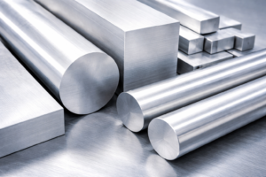
- 6082 (Europe) / 6061 (common in US): Great general-purpose choice; good strength, good corrosion resistance, weldable, widely available.
- 7075: Higher strength; excellent for structural parts and high-load applications, but less corrosion-resistant and not typically used where welding is required.
- 2014 / 2024: Strong and fatigue resistant; often used in aerospace contexts, but corrosion resistance can be lower and protection/finishing becomes more important.
- 5083: Excellent corrosion resistance (marine environments); machining can be different from 6xxx alloys and surface finish expectations should be aligned.
- MIC-6 / cast tooling plate: Stable and flat; useful for fixture plates, jigs, and parts where flatness matters more than maximum strength.
Practical tip: If you need tight flatness on a plate-like part, consider specifying stress-relieved plate or tooling plate where appropriate. It can reduce the risk of movement after machining.
Aluminium Milling vs Turning: Which is Best for Your Part?
It’s common for parts to include both milled and turned features. The best route depends on geometry and what needs to be controlled. If your part is primarily rotational (shafts, hubs, rings), turning is often faster and more concentric by nature. If it’s prismatic (flat faces, pockets, mounting patterns), milling is usually the right base process. For hybrid components, many suppliers will choose a process chain that reduces setups – sometimes starting on a lathe and finishing on a mill, or using mill-turn equipment where appropriate.
Before you commit to a process, think about what must be true for the part to work: concentricity, perpendicularity, flatness, or positional accuracy. The process should be chosen to “naturally” hold those characteristics, not fight them.
3-Axis vs 5-Axis Aluminium Milling
Many aluminium parts can be made efficiently on 3-axis machines. The move to 4- or 5-axis is most valuable when it reduces setups, improves access, or maintains datum consistency for complex geometry. A 5-axis approach can help when you have:
- Features on multiple faces that need tight positional control
- Angled holes, chamfers, or contoured surfaces
- Deep pockets or hard-to-reach regions where tool length becomes an issue
- Cosmetic surfaces where you want consistent finishing passes without re-clamping marks
Even then, “5-axis” isn’t automatically better. Sometimes it’s smarter (and cheaper) to fixture a part well and run it in two or three controlled setups on 3-axis equipment. A good aluminium milling service will choose the method that improves repeatability and reduces risk, not just the one that sounds most advanced.
Surface Finish and Deburring for Aluminium Parts
Aluminium can achieve excellent cosmetic and functional finishes, but the approach depends on the alloy and the end requirement. Finishing also links closely to burr control – especially around small holes, thin edges, and intersecting features. Common finish considerations include:
- Toolpath strategy (climb vs conventional finishing, stepovers, scallop height control)
- Cutter selection (sharp geometries designed for aluminium, polished flutes)
- Edge break definition (a clear instruction beats “deburr all edges” guesswork)
- Handling and protection (soft packaging, separators, masking for critical faces)
If you need a specific surface roughness (Ra), specify it on the drawing for the surfaces that matter. If it’s cosmetic, consider a finishing method that suits production volumes – bead blasting can hide minor tool marks, while fine machining finishes can look excellent but may show directional patterns.
Aluminium Anodising and Post-Machining Finishes
Many aluminium components are finished after milling for corrosion resistance, wear, or appearance. Anodising is one of the most common, but it affects dimensions and should be considered early. Key planning points:
- Anodising builds up an oxide layer; dimensional impact depends on type and thickness.
- Masking may be needed for critical fits, threads, or electrical contact points.
- Sharp corners may “burn” or show uneven coating; small radii can help.
- Certain alloys (especially high-copper types) may anodise with different colour response.
Other finishing options include chemical conversion coatings, paint/powder coat, hard anodise for wear, or leaving parts as-machined when environment allows. If you’re unsure, your supplier can advise based on alloy and use case. Tarvin Precision, for instance, will typically want to know whether you’re targeting cosmetic uniformity, wear resistance, or corrosion protection, because the best finishing route isn’t the same for all three.
Design for Manufacturability in Aluminium Milling
Aluminium is forgiving, but your design choices still have a major impact on cycle time, scrap risk, and repeatability. A DFM (design for manufacture) pass can often reduce cost without changing function. Most milling cost comes from tool engagement time, tool changes, and difficult access. Designs that allow short, rigid tools and consistent toolpaths tend to be faster, cleaner, and more repeatable.
- Avoid deep, narrow pockets where only long tools can reach; consider opening the pocket or splitting the part.
- Use sensible internal corner radii to match standard cutter sizes (bigger radii usually machine faster).
- Limit ultra-thin walls unless necessary; if needed, support them with ribs or leave stock for a final finishing pass.
- Define datums clearly so the shop can plan setups that protect positional accuracy.
- Add chamfers or radii intentionally rather than leaving “sharp” edges that must be guessed during deburr.
- Keep threads realistic for aluminium (engagement length, helicoils where needed, and avoiding tiny fragile taps).
Even small changes – like increasing a fillet from 0.5 mm to 2 mm – can make a big difference in tool choice and machining stability.
Workholding and Distortion Control in Aluminium Milling
Aluminium parts, especially plate-like components, can move when material is removed. This comes from residual stresses in the stock and from clamping pressure during machining. A reliable aluminium milling service will manage distortion by:
- Choosing appropriate stock (stress-relieved plate where needed)
- Using fixtures that distribute clamping forces evenly
- Balancing material removal on both sides where possible
- Leaving finishing stock and performing final passes after the part has “settled”
- Planning operations so datums are maintained with minimal re-clamping error
If your part has tight flatness or parallelism, it’s worth discussing early. Sometimes the best solution is process-based (sequence and fixturing), and sometimes it’s material-based (switching to tooling plate or adjusting thickness).
Aluminium Prototyping to Production
Many projects start with prototypes and then move into low-volume or serial production. The best machining approach can change across those phases, and planning for that transition helps avoid surprises. In prototyping, the goal is usually speed and learning: you might accept slightly higher unit cost to get parts quickly and validate fit/function. As you move into production, attention shifts to repeatability and unit economics – better fixtures, dedicated tools, and process control become more valuable. Typical production improvements include:
- More efficient workholding (soft jaws, dedicated fixtures)
- Reduced setups (combining operations, better datum strategy)
- Tool life optimisation (more stable cutters and consistent feeds)
- In-process probing and inspection routines to control drift
- Documented process plans for repeatable outcomes batch-to-batch
A supplier that can support both prototype and production aluminium milling can help you avoid redesigns later by making early recommendations that scale.
RFQ Checklist: What to Send an Aluminium Milling Service
The fastest way to get accurate pricing and lead times is to send complete, unambiguous information. Even a great drawing can benefit from a short note that clarifies priorities. Quotes are quickest and most accurate when the shop can clearly see your functional intent, finishing requirements, and any inspection expectations.
- 3D CAD + 2D drawing (STEP + PDF is a common combination)
- Material and temper (e.g., 6082-T6, 7075-T6)
- Quantity and expected repeat orders (prototype vs ongoing batches)
- Tolerances and GD&T clearly defined; highlight critical features
- Surface finish requirements (Ra targets, cosmetic faces, edge breaks)
- Finishing/coating requirements (anodise type, masking needs)
- Inspection needs (FAI, CMM reports, certificates, traceability)
- Target lead time and any constraints (delivery windows, phased quantities)
If you’re working to an industry standard or quality system expectation, mention it up front, especially for regulated sectors where traceability and documentation matter.
Quality and Inspection for Aluminium Milled Components
Quality isn’t only about measuring the final part, it’s about controlling the process so parts don’t drift out of tolerance as tools wear or temperatures change. For aluminium milling, good inspection practice often includes:
- Clear identification of critical-to-quality features
- Consistent datum strategy from machining through inspection
- Appropriate measurement tools for the tolerance level (and part geometry)
- Calibration control and documented inspection results where required
If your parts interface with bearings, seals, optics, or precision assemblies, share that context. It can influence decisions like finishing passes, tool selection, and whether to use probing to control feature location during machining.
Common Pitfalls When Sourcing an Aluminium Milling Service
Most issues aren’t dramatic, they’re small misunderstandings that show up later as assembly problems, cosmetic dissatisfaction, or inconsistent fit. You get the best results when the drawing tells the shop what matters, and the shop tells you what assumptions it’s making.
- Over-tolerancing non-critical features, driving unnecessary cost
- Unclear edge condition leading to sharp edges or excessive chamfering
- Not accounting for anodising build-up on critical fits
- Assuming all aluminium behaves the same, regardless of alloy/temper
- Thin-wall distortion surprises when machining plate-like parts
- Missing datum intent, causing positional errors across multiple setups
- Cosmetic expectations not stated, leading to visible toolpath patterns
A short DFM conversation early can prevent most of these.
Choosing the Right Aluminium Milling Partner
A strong aluminium milling service is defined less by the headline machine list and more by how they control risk: fixturing strategy, programming discipline, inspection capability, and communication. Look for signs like:
- Willingness to discuss DFM and datum strategy
- Clear approach to tolerances, inspection, and finishing
- Evidence of repeatability (process notes, inspection reporting, traceability where needed)
- Practical guidance on alloy choice and post-machining finishing
It’s also worth choosing a supplier who can explain trade-offs in plain language. When Tarvin Precision supports aluminium milling work, the most useful conversations tend to be about what to prioritise – speed, aesthetics, tolerance, or long-term repeatability, so the process is built around the real requirement rather than assumptions.
Getting the Most from an Aluminium Milling Service
Aluminium milling is one of the most versatile manufacturing routes available – fast enough for prototyping, precise enough for demanding assemblies, and scalable into production with the right planning. The difference between “it’ll do” and “it fits perfectly every time” usually comes down to a few fundamentals: correct alloy selection, sensible tolerancing, clear datums, good workholding, and finish requirements that are specified rather than assumed.
If you treat your supplier as a technical partner – sharing context, highlighting what matters, and inviting a DFM pass – you’ll get better parts, fewer iterations, and more predictable lead times from your aluminium milling service.