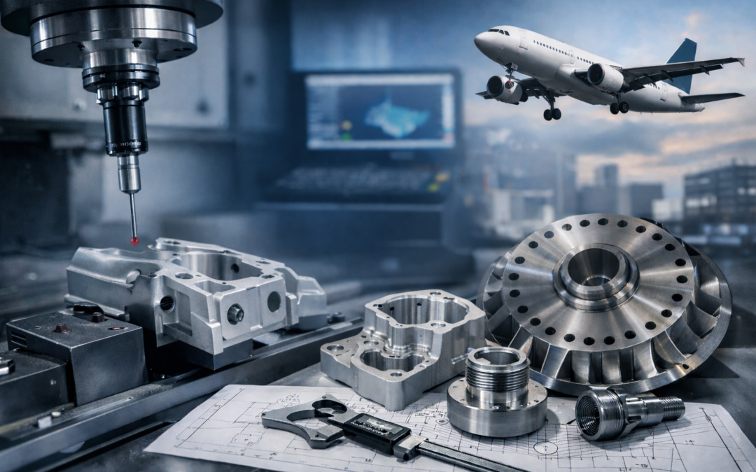
Aerospace parts machining sits at the intersection of extreme performance requirements and uncompromising quality control. Whether you’re producing flight-critical brackets, engine-adjacent components, UAV structures, or complex housings, the expectations are the same: consistent accuracy, robust documentation, and repeatable processes that stand up to scrutiny.
This guide explains what “good” looks like in aerospace parts machining – covering materials, processes, tolerances, inspection, traceability, and how to choose a capable supplier. It’s written for engineers, buyers, and quality teams who want fewer surprises between design intent and delivered parts.
What Makes Aerospace Parts Machining Different?
Aerospace isn’t just “tight tolerance machining.” It’s tight tolerance machining plus controlled processes, proven inspection capability, and a paper trail that can be audited. Parts often operate under vibration, temperature cycling, fatigue loading, and corrosive environments. That means small deviations in geometry, surface condition, or material pedigree can become big problems later. In practice, aerospace parts machining typically demands:
- Higher emphasis on process control and repeatability than one-off precision work
- Stronger requirements for material certification and traceability
- More frequent use of advanced alloys and challenging geometries
- Inspection plans that go beyond “measure a few key dims”
- Quality systems aligned to aerospace expectations (e.g., AS9100)
Common Aerospace Machined Components and Typical Features
Aerospace machining spans everything from structural parts to fluid systems and electronics enclosures. Even “simple” parts often include features that require careful planning: thin walls, deep pockets, intersecting bores, sealing faces, or critical datums that control assembly alignment. You’ll commonly see features such as:
- Thin-wall ribs, webs, and lightweighting pockets
- Precision bores for bearings, bushings, or hydraulic seals
- Thread forms including inserts, lockwire features, and special callouts
- O-ring glands and sealing surfaces with controlled finish
- Datum structures that manage stack-up across multi-part assemblies
- Complex 3D surfaces (particularly with 5-axis CNC machining)
CNC Machining for Aerospace Parts: Core Processes and Where They Fit
Most aerospace parts machining is based around CNC milling and turning, often supplemented with secondary processes for accuracy, surface finish, or special features. The “best” process used by an AS9100 machine shop is usually the one that hits your functional requirements with stable capability and minimal risk, not necessarily the most exotic method. Typical process options include:
- 3-axis CNC milling for prismatic parts, pockets, faces, drilling patterns
- 4-axis / 5-axis CNC machining for complex surfaces, multi-side access, reduced setups
- CNC turning for rotational parts like sleeves, spools, shafts, and rings
- Mill-turn / multitasking for parts needing both turned and milled features in one cycle
- EDM (wire/sink) for hard materials, sharp internal corners, delicate features
- Grinding / honing / lapping for tight form control and low Ra finishes
- Broaching / slotting (sometimes) for keyways, splines, or special internal forms
Aerospace Materials Machining: Aluminium, Titanium, Stainless and Nickel Alloys
Material selection drives machinability, tool choice, cycle time, and quality risk. Aerospace designers often prioritise strength-to-weight, fatigue performance, and temperature capability – then the machining team has to deliver geometry without compromising material integrity.
Aluminium alloys (e.g., 6061, 6082, 7075) machine well and suit many structural parts. Titanium alloys (like Ti-6Al-4V) offer excellent strength-to-weight and corrosion resistance but generate heat at the cutting edge and demand careful parameter control. Stainless steels vary widely in machinability; some grades work cleanly while others work-harden quickly. Nickel-based superalloys (e.g., Inconel) are among the most demanding—often chosen for temperature performance where tool wear and heat management are constant constraints. When planning aerospace parts machining, account for:
- Material condition (solution treated, aged, annealed, etc.)
- Grain direction and plate/forging considerations for fatigue-critical parts
- Distortion risk after heavy stock removal
- Compatibility with downstream treatments (anodise, passivation, plating, etc.)
High Precision Tolerances in Aerospace Parts Machining
Not every aerospace component needs micron-level tolerances, but many need predictable tolerances and controlled geometry. The biggest gains often come from designing tolerances around function and assembly data – then applying inspection methods that verify what truly matters.
A few practical points: tight tolerances increase cost non-linearly; they may also increase lead time because parts can require additional finishing passes, stabilisation time, or more extensive inspection. Equally, a “loose” tolerance with poor datum definition can be more expensive than a tighter tolerance that’s properly structured. In aerospace parts machining, tolerance performance is typically managed through:
- Stable workholding and known datum strategies
- Minimising setups (5-axis or mill-turn can help)
- Toolpath strategies that reduce heat and cutting force
- Controlled measurement plans (in-process checks + final verification)
Surface Finish and Edge Condition for Aerospace Machined Components
Surface finish isn’t only cosmetic. In aerospace, it influences sealing performance, friction and wear, fatigue behaviour, and corrosion initiation. Edge condition matters too: burrs can break off and contaminate assemblies, while sharp edges can become crack starters in fatigue-loaded parts.
To make surface requirements actionable, drawings should define finish where it matters (e.g., sealing faces, bearing seats) and allow more relaxed finishes where it doesn’t. The shop then chooses tooling and finishing processes accordingly. Common finishing considerations include:
- Specified Ra on functional surfaces (with measurement method defined)
- Burr control and consistent deburring approach (manual + controlled tools)
- Edge break callouts (e.g., “break sharp edges 0.2–0.5 mm” where appropriate)
- Avoiding surface damage from handling, clamping, or rework
Aerospace Coatings and Post-Machining Treatments
Post-machining treatments are often essential, but they introduce their own risks: dimensional change, masking complexity, hydrogen embrittlement concerns (for some processes/materials), and finish variation. A good machining plan anticipates these changes early – especially for tight tolerance bores, threads, and sealing features.
Typical aerospace treatments include anodising (common for aluminium), passivation (for stainless), plating, heat treatment, shot peening, and dry film lubrication. The key is to define what must be controlled before treatment (e.g., pre-plate dimensions) and what must be verified after. When specifying treatments for aerospace parts machining, consider:
- Thickness build-up and where it matters (bores, threads, mating faces)
- Masking requirements and any “no-coat” zones
- Inspection points before and after treatment
- Documentation needed from approved processors
Design for Manufacturability in Aerospace Parts Machining
Design for manufacturability (DFM) is where time and budget are most often saved – without compromising performance. Small geometry tweaks can eliminate special tooling, reduce setups, and improve repeatability. DFM doesn’t mean loosening the design; it means aligning design intent with stable manufacturing capability.
Early DFM review commonly focuses on wall thickness, tool access, corner radii, and datum structure. Deep pockets with sharp internal corners, for example, push cycle time and increase chatter risk. Similarly, long slender features can deflect during machining, affecting both tolerance and surface finish. Helpful DFM levers include:
- Adding internal radii that match standard cutter sizes
- Avoiding extreme length-to-diameter ratios in holes where possible
- Defining clear datums that reflect assembly and inspection needs
- Using tolerances that control function rather than “tight everywhere”
- Planning for post-treatment changes (anodise, heat treat, etc.)
Inspection and CMM Measurement in Aerospace Parts Machining
Inspection is not a final “tick-box”, it’s part of the manufacturing process. Many aerospace components benefit from in-process measurement to catch drift early (tool wear, thermal growth, fixture movement) and reduce scrap risk.
Coordinate Measuring Machines (CMMs) are common for complex geometry and GD&T verification, but they’re only as good as the inspection plan: datum alignment, probing strategy, and environmental control (temperature stability) all matter. For some features, dedicated gauges, bore mics, air gauges, or surface roughness testers are more appropriate than CMM probing. A robust inspection approach often includes:
- First-off inspection and documented setup validation
- In-process checks on key characteristics (KCs)
- Final inspection with traceable measuring equipment
- Clear reporting aligned to drawing requirements (dims, GD&T, finish)
Traceability and Documentation: Material Certs, Batch Control and Records
Traceability is one of the defining pillars of aerospace precision manufacturing. It’s not enough to make a good part – you must also prove what it is, what it’s made from, and how it was controlled. Requirements vary by programme, but material certification and batch identification are common expectations.
Shops typically manage traceability through controlled goods-in procedures, material identification, route cards/travellers, and retention of inspection records. If your parts are going into regulated supply chains, you may also need records for special processes, calibration, and nonconformance handling. Documentation frequently includes:
- Material certificates (and certificate review at goods-in)
- Batch/heat/lot traceability through production
- Inspection reports (first article where required)
- Calibration records for measurement equipment
- Nonconformance reports and concession workflows (when applicable)
AS9100 and Aerospace Machining Standards: Why They Matter
AS9100 is widely recognised as a quality management standard tailored to aerospace. It builds on ISO 9001 with additional requirements focused on risk management, product safety, configuration control, and stronger oversight of suppliers and processes. For many customers, AS9100 isn’t just a nice-to-have; it’s a gatekeeper to doing business.
If you’re buying aerospace parts machining services, an accredited AS9100 machining supplier typically signals a more mature quality system – though you should still assess technical capability, inspection capacity, and programme fit. Tarvin Precision, for example, is AS9100 accredited and based in Deeside, UK – an area with a long-standing aerospace manufacturing presence. Mentioning that isn’t about sales hype; it’s about the practical reality that aerospace supply chains often cluster in regions with established skills, supporting services, and quality expectations.
Choosing a UK Aerospace Machining Supplier: Capability Checks That Reduce Risk
Selecting a machining partner for aerospace should be less about glossy promises and more about evidence: proven processes, inspection capability, materials handling, and communication. A strong supplier will ask clarifying questions, challenge ambiguous callouts, and propose a controlled plan rather than guessing. When you’re assessing aerospace parts machining suppliers, look for signals of real capability:
- Quality system maturity (e.g., AS9100, internal audit cadence, NCR handling)
- Evidence of repeatability (process control, documented setups, training)
- Inspection capacity (CMM access, calibrated equipment, reporting)
- Experience with your materials and post-treatments
- Clear communication on lead time, risk, and change control
If you’re sourcing in the UK, it can help to work with suppliers in established aerospace corridors. Deeside is one such area, and Tarvin Precision’s presence there – along with AS9100 accreditation – fits the kind of environment where aerospace requirements are familiar, not exotic.
Cost and Lead Time Drivers in Aerospace Parts Machining
Aerospace cost is rarely just “machine time × hourly rate.” The biggest drivers are often complexity, tolerance strategy, material behaviour, and inspection burden. A part with moderate machining but extensive verification and documentation can cost more than a geometrically complex part with fewer regulated requirements.
Lead time is similarly influenced by external dependencies: special material procurement, approved processors for treatments, and inspection scheduling. The best way to reduce both cost and lead time is to address risk early – DFM review, clear drawings, and realistic tolerance schemes. Common cost/lead-time drivers include:
- Tight tolerances on features that are difficult to measure or control
- High stock removal causing distortion and extra finishing passes
- Challenging alloys (titanium, Inconel) and high tool wear
- Multiple setups due to poor access or datum strategy
- Post-processing steps with limited approved capacity
- Documentation requirements (FAI, detailed inspection reporting)
Practical Checklist for Aerospace Parts Machining Success
Aerospace programmes move faster when engineering, quality, and manufacturing agree early on what “done” means. The goal is to avoid late-stage clarifications, rework loops, or inspection disputes. Use this checklist as a starting point:
- Confirm material grade, condition, and certification requirements
- Define functional datums and align GD&T to inspection reality
- Identify key characteristics and plan in-process checks
- Review post-treatment impacts (thickness build-up, distortion)
- Specify finish where it matters, not everywhere
- Agree on documentation deliverables (FAI, CoC, inspection reports)
- Validate packaging requirements to protect critical surfaces
FAQ: Aerospace Parts Machining
These are some of the most common questions people ask when specifying or sourcing aerospace parts machining. The answers below are intended as practical guidance to help you set realistic requirements and avoid delays at inspection and delivery.
What tolerances are realistic for aerospace CNC machining?
Realistic tolerances depend on part size, material, geometry, and inspection method. Many features can be held tightly with stable processes, but cost rises quickly as tolerances tighten – especially on thin walls, deep pockets, or hard-to-measure GD&T. A supplier DFM review is often the fastest way to set sensible targets.
Is 5-axis CNC always better for aerospace parts machining?
Not always, but it often helps. 5-axis can reduce setups, improve access, and maintain datum consistency, especially on complex parts. For simpler geometries, 3-axis machining with good fixturing may be more cost-effective and equally capable.
How important is AS9100 when choosing a machining supplier?
AS9100 is a strong indicator of a quality system aligned to aerospace expectations, particularly around risk, traceability, and controlled processes. It doesn’t automatically guarantee technical capability, but it does reduce certain compliance risks—especially in regulated supply chains.
What documents should I expect with aerospace machined components?
Common deliverables include material certificates, certificates of conformance, inspection reports, and (when required) first article inspection documentation. Requirements vary by customer and programme, so it’s best to define them clearly in the purchase order.
Aerospace Parts Machining Done Right
If you’re planning a new project or reviewing an existing supply chain, the fastest way to de-risk aerospace parts machining is to confirm three things early: material certification and traceability, a clear datum/tolerance strategy, and an inspection plan that matches the drawing intent. At Tarvin Precision (AS9100 accredited) in Deeside, UK – an area well known for aerospace manufacturing – we treat DFM feedback, controlled processes, and documented inspection as standard parts of the workflow, so customers get consistent parts and consistent paperwork without the drama.