CNC components sit quietly behind a huge amount of modern engineering – inside analytical instruments, automation cells, medical devices, aircraft subassemblies, energy systems, and high-end consumer products. The reason is straightforward: CNC machining offers a dependable route to accurate parts, made from a wide range of materials, with repeatable quality from prototype to production.
This guide is written for engineers, buyers, and project leads who need CNC components that fit first time, perform reliably, and arrive when promised. It covers what “good” looks like in CNC manufacturing, what drives cost and lead time, and how to make design choices that reduce risk without compromising function. You’ll also find practical advice on drawing notes, inspection planning, surface finishes, and common pitfalls. Along the way, we’ll reference the real-world approach used by experienced subcontract machinists such as Tarvin Precision – focused on manufacturability, consistency, and clear communication rather than hype.
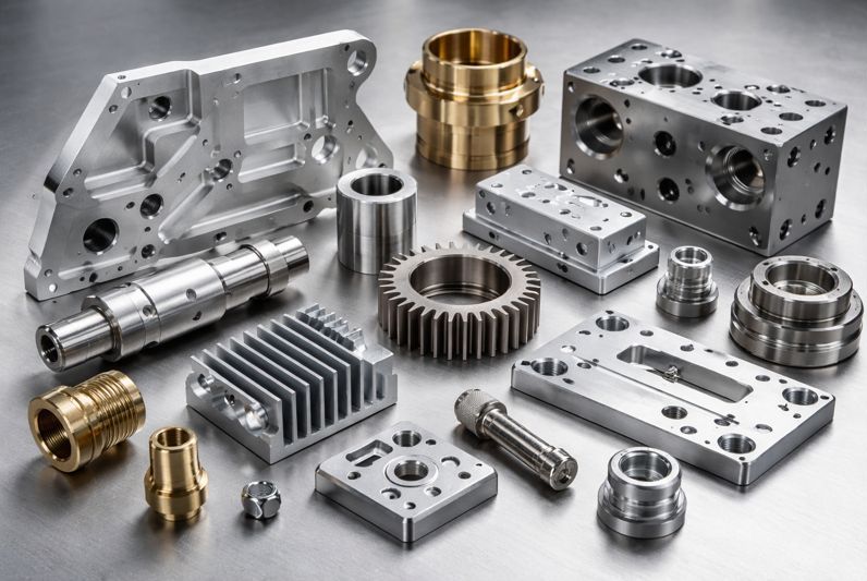
What Are CNC Components and Why Are They Used?
CNC components are parts manufactured using Computer Numerical Control machining processes – most commonly milling and turning – where cutting tools remove material to achieve a specific geometry. Unlike forming or moulding, CNC machining creates the final shape by precision material removal, which makes it ideal for complex geometries, tight tolerances, and frequent design iterations.
CNC components are popular because they’re versatile. You can machine aluminium for lightweight stiffness, stainless steel for corrosion resistance, brass for stable precision, or engineering plastics for electrical insulation and low friction. For product development teams, CNC also offers speed: you can go from CAD model to functional part in days rather than weeks, especially when the supplier can advise on design-for-manufacture (DFM) early.
Typical applications for CNC components include:
- Precision housings and enclosures for instrumentation
- Mounting brackets, clamps, and fixtures
- Shafts, couplings, and bearing seats
- Fluid fittings, manifolds, and valve bodies
- Heat sinks and thermal spreaders
- Insulating components and wear parts in plastics
CNC Component Manufacturing Methods: Milling vs Turning vs Multi-Axis
How CNC components are made affects accuracy, finish, cost, and even performance. The best method is usually the one that makes critical features in the fewest setups, with stable workholding, and good tool access.
CNC milling is typically used for prismatic parts – flat faces, pockets, slots, and complex 3D surfaces. CNC turning is ideal for rotational parts – shafts, bushes, spacers, threaded features, and concentric diameters. Multi-axis machining (such as 4-axis and 5-axis) adds the ability to machine multiple faces or angled features in one operation, which can improve positional accuracy by reducing re-clamping.
A helpful rule of thumb: if your CNC component can be made in fewer setups, it will usually be more consistent and potentially lower risk – especially for geometric tolerances that depend on datums across multiple faces.
Common machining routes for CNC components:
- 3-axis milling for general brackets and plates
- 3-axis mill + second op for features on the reverse side
- CNC turning for concentric cylindrical components
- Mill-turn (live tooling) for parts combining milled flats + turned diameters
- 5-axis machining for angled features, ports, and complex pockets
Designing Machined Components for Manufacturability
Good CNC components start with good design decisions. You don’t need to “design for the machine” at the expense of function – but you do want to avoid geometry that forces slow machining, fragile tools, or repeated setups. DFM isn’t about dumbing down; it’s about getting the same performance with fewer manufacturing compromises.
The biggest wins usually come from: selecting sensible tolerances, choosing stable datums, avoiding unnecessary deep pockets, and specifying finishes only where they matter. Practical component manufacturers can often suggest small geometry tweaks that preserve your intent while reducing cost and lead time. That kind of feedback loop is something established suppliers (including Tarvin Precision) typically encourage early in the process.
Design tips that usually improve CNC component outcomes:
- Add internal corner radii (bigger is usually easier and stronger)
- Avoid very deep, narrow pockets unless truly required
- Prefer standard drill sizes and thread forms where possible
- Use consistent wall thickness to reduce distortion
- Align critical features to a common datum structure
- Consider tool access and clamping faces early
Tolerances for Components: What’s Realistic and What’s Expensive?
Tolerance strategy is one of the biggest levers you have. Over-tightening tolerances across a whole drawing can multiply inspection time, scrap risk, and machining effort, often without improving the function of the final assembly.
A better approach is to tolerate CNC components based on function. Tighten tolerances only on the features that control fit, sealing, motion, or optical alignment. Leave non-critical features looser. And be specific: a general note like “all dimensions ±0.01” can create accidental cost.
Practical tolerance guidance for CNC components:
- Use “tight” tolerances only where assembly demands it
- Call out datums and GD&T on critical relationships rather than chasing every dimension
- Avoid stacking unnecessary tolerances across multiple features
- Consider the measurement method: if it’s hard to measure, it will be hard to control
Examples of features that often justify tighter tolerances:
- Bearing bores and shaft fits
- Mating faces for seals or gaskets
- Precision alignment features (dowel holes, datum pads)
- Optical or metrology-related mounting points
Materials for CNC Components: Choosing the Right Metal or Plastic
Material selection affects machinability, stability, strength, corrosion resistance, and thermal behaviour. It also affects lead time—especially if you need certified material or specific heat treatments.
Aluminium alloys (like 6082 and 7075) are common for CNC components because they’re lightweight and machine cleanly. Stainless steels are used when strength, temperature resistance, or corrosion performance matters. Machining CNC brass parts can be excellent for stable, clean machining and fine threads. Engineering plastics are often chosen for insulation, low friction, chemical resistance, or weight reduction.
Your supplier can help you match material to real-world requirements: not just strength on a datasheet, but how it behaves during machining and in service. This is where a manufacturing partner who understands end-use contexts – like laboratory instruments, automation, or aerospace-adjacent requirements – can add value without being “salesy”.
Common material choices for CNC components:
- Aluminium: lightweight, good machinability, easy anodising
- Stainless steel: durability, corrosion resistance, higher machining effort
- Mild steel: cost-effective, often used with plating or paint
- Brass: excellent machinability, good for fittings and precision threads
- PEEK / acetal / nylon: plastics for wear, insulation, and chemical exposure
Surface Finish for CNC Parts: When It Matters
Surface finish is often specified without considering the functional need. A cosmetic finish on an internal pocket that nobody sees is usually wasted cost. On the other hand, surface finish can be critical for sealing faces, sliding surfaces, optical mounts, and fatigue performance.
Be clear about what you need: define a surface roughness (Ra) requirement on critical faces, call out deburring expectations, and specify cosmetic requirements only where visible. If you need consistent appearance across batches, mention it – colour variation (especially on anodised aluminium) can surprise people if it’s not discussed early.
Where surface finish is functionally important:
- Sealing faces and gasket lands
- Bearing seats and sliding interfaces
- Optical interfaces and precision reference pads
- Parts with fatigue or stress concentration sensitivity
Common finishes for CNC components:
- As-machined (with deburr)
- Bead blasted (uniform matte appearance)
- Anodised aluminium (clear or dyed)
- Passivated stainless steel
- Plated steels (zinc, nickel, etc., as required)
Deburring and Edge Breaks: Small Notes, Big Impact
Deburring might sound like a minor detail, but it’s one of the most common causes of assembly issues. Sharp edges can cut seals, snag cables, interfere with fits, or create handling hazards. Burrs can prevent proper seating and distort measurement results.
A simple, explicit drawing note can prevent confusion: define an edge break (for example, “break sharp edges 0.2–0.5 mm” or “deburr and break all edges”). If a particular edge must remain sharp (rare, but sometimes needed), call it out.
Good practice for CNC components:
- Add a general note for deburr/edge break
- Identify any protected surfaces that must not be blasted or tumbled
- Specify “no burrs” for threads, cross-holes, and bores
- Consider how parts will be handled and assembled
Inspection and Quality for CNC Machined Parts
Inspection requirements should align with risk. Prototype parts may only need basic dimensional checks, while regulated industries may require traceability, calibrated inspection equipment, and controlled documentation.
If your CNC components have critical fits, consider defining a measurement plan: what gets checked, how, and at what frequency. For production, you might specify first article inspection (FAI) and then reduced sampling once the process is proven stable.
A capable machine shop will typically guide you here. Tarvin Precision, for example, often supports customers by clarifying critical-to-quality features and aligning inspection effort with the real function of the part—helping avoid both under-checking (risk) and over-checking (cost).
Inspection considerations that reduce surprises:
- Specify datums and measurement references clearly
- Use GD&T where relationships matter most
- Clarify whether threads need gauge checks
- State any certificate requirements (material certs, CoC, etc.)
- Consider environmental sensitivity (temperature effects on measurement)
Lead Time for CNC Components: What Drives It?
Lead time isn’t just “machine time.” It includes planning, programming, tooling, material procurement, setup, machining, deburr, finishing, inspection, and packaging. Any external processes – anodising, heat treatment, plating, engraving – add complexity and potential schedule variability.
Design changes late in the process can also reset lead time, particularly if they impact datums, workholding, or the manufacturing route. If you anticipate iterations, share that early. Many teams choose to machine early prototypes in a “development-friendly” way, then optimise for production once the design stabilises.
Typical lead-time drivers for CNC components:
- Non-stock material or special certification needs
- Multiple setups or complex workholding
- Tight tolerances requiring slower machining + more inspection
- External finishing processes and transport time
- High part count with extensive manual deburr/handling
Cost Drivers in CNC Components Production
Understanding cost drivers helps you prioritise the right changes. Most CNC component cost comes from time: programming time, setup time, cycle time, and inspection time. Material cost matters, but it’s often secondary unless you’re using expensive alloys or large billets with heavy material removal.
Reducing setups is usually the biggest win. The next wins come from smarter tolerance assignment, avoiding features that require specialist tooling, and considering whether a part could be made from plate, bar, or near-net stock.
Common cost drivers for CNC components:
- Very tight tolerances across many features
- Deep pockets and small internal radii
- Thin walls that cause distortion
- Difficult materials (tough stainless, exotic alloys)
- High cosmetic expectations requiring extra processing
- Complex GD&T that demands specialist metrology
Prototypes to Production: Scaling Without Redesign
One advantage of CNC is that you can prototype and produce using similar processes. But scaling smoothly still requires thought. A prototype might be made with extra manual finishing, more conservative feeds and speeds, or more frequent inspection. In production, you want predictable process capability and reduced touch time.
If you expect to scale, ask your supplier how the process will change from prototype to batch. Sometimes a small tweak – like adding a locating feature or a better clamping land – can enable a more repeatable manufacturing route. It’s also worth thinking about part families: if you can standardise blanks or shared features across multiple CNC components, you can reduce setup time and speed up delivery.
Practical ways to improve scalability:
- Define critical features for process control early
- Keep datum schemes consistent across part revisions
- Use standard hardware and common thread sizes
- Avoid “prototype-only” geometry that can’t be repeated
- Consider part marking or revision identification if needed
Common Mistakes When Specifying CNC Components
A few repeated issues cause disproportionate pain in CNC projects. The good news is they’re preventable with small changes to drawings, communication, and early review.
The most common mistakes include: unclear datums, over-tolerancing, missing deburr notes, ambiguous surface finish requirements, and not accounting for finishing thickness. Another big one is assuming the supplier will interpret intent correctly when the drawing is vague – machinists are good, but they can’t read minds.
Mistakes that frequently cause rework or delays:
- Blanket tight tolerances without functional justification
- No datum scheme for parts with complex geometry
- Specifying anodise/plating without considering dimensional impact
- Underspecified threads (class, depth, gauge requirements)
- Cosmetic requirements not clearly defined
- Forgetting tool access for deep or narrow features
How to Prepare Better Drawings and RFQs
Clear RFQs and drawings shorten lead time and reduce the number of “back-and-forth” questions. If you want a smooth process, provide the latest revision, a 2D drawing (even if you also send a 3D model), material specification, finish requirements, and a short note about what features are critical.
If you already know the part’s application (even generally), share it. Knowing whether a part is a cosmetic enclosure, a precision alignment feature, or a load-bearing bracket changes how a machinist thinks about risk, inspection, and finishing.
What to include in an RFQ for CNC components:
- Quantity and delivery expectation
- Drawing revision + 3D model if available
- Material spec + certification needs
- Surface finish + any external processes
- Critical tolerances and functional features
- Inspection requirements (FAI, CoC, etc.)
- Any packaging or handling constraints
CNC Components and Supplier Selection: What to Look For
Choosing a supplier isn’t just about unit price. For CNC components, you’re buying reliability: consistent dimensions, predictable delivery, and someone who flags issues before they become expensive problems.
Look for responsiveness, clear questions, evidence of process control, and the ability to explain trade-offs. A shop that offers practical DFM feedback can save you money and time – especially during early design stages. This is why many engineering teams keep a shortlist of suppliers they trust for complex work, and why firms like Tarvin Precision build long-term relationships by being straightforward about feasibility, tolerances, and lead times.
Signals of a strong CNC components supplier:
- Clear communication and fast clarification questions
- Practical DFM suggestions without pushing unnecessary changes
- Capability to inspect what they machine
- Traceability options when required
- Consistent approach from prototype through batch work
Final Checklist for Successful CNC Components
Before you place your next order, it helps to do a quick sanity check. Most issues can be avoided with a five-minute review of the drawing and a short conversation with your machinist.
A practical pre-order checklist:
- Confirm material, finish, and any certification requirements
- Identify critical-to-function dimensions and tolerances
- Check datum scheme and GD&T clarity (if used)
- Add deburr/edge-break notes and thread specifications
- Consider finishing thickness and masking requirements
- Ensure the drawing revision matches the model and RFQ
- Agree on inspection expectations for critical features
CNC components are one of the most flexible ways to turn designs into real, working hardware, fast. With sensible tolerances, clear drawings, and a supplier who engages early, you can reduce iteration cycles, improve first-time fit, and keep costs predictable as you scale. If you’re working with an experienced machining partner such as Tarvin Precision, the best results usually come from treating the process as collaborative: specify what matters, stay open to practical DFM, and keep communication crisp from revision to revision.